background image

21 

246.805.201  


Date: 2017-09-26


DMX 

channel 

Function  Description 

Position 

rough 

This channel controls the position of the winch, with the speed (DMX channel 3). 
This rough position works together with the fine position (DMX channel 2). 
The rough position and the fine position are multiplied in to a 16 bit channel. The 

rough position is the MSB

Position 

fine 

This channel controls the position of the winch, with the speed set on DMX 

channel 3. 
This fine position works together with the rough position (DMX channel 1). 
The fine position and the rough position are multiplied in to a 16 bit channel. The 

fine position is the LSB

Speed 

This channel controls the speed and defines the max lifting/lowering speed of the 

winch. 
The winch runs with the set max speed, but slows down as closing in on the 

wanted position. 
This channel also works as a main brake; the motor does not run unless the 

channel is set above 0%. 
The speed-channel can also be used to make soft and slow movements or fast and 

sudden movements. 

Motor 

enable 

Channel 4 is used as an extra security channel. The value on channel 4 needs to be 

between 50 and 55 %, for the motor to run.  
All other values make the motor stop.  
All other values will also reset any error shown. 
All other values will save the current position before a power down. 

Reset UP 

There is a 3s delay on this channel to reduce risk of accidentally resetting the top 

position. 
Channel 5 is used to manually move the wire up. When channel 5 is set ≥ 10% the 

winch will move up until it reaches the limit switch UP. 10 – 100% makes the 

motor run up, at variable speed.  (10% = low speed – 100% = full speed). 
Setting DMX channel 5 to 0 resets the position. 

Manual 

DOWN 

There is a 3s delay on this channel to reduce risk of accidentally setting a new 

range. 
Channel 6 is used to manually move the wire down.  When channel 6 is set ≥ 10% 

the winch will move down, until it reaches the DOWN limit switch. 10 – 100% 

makes the motor run down, at variable speed. (10% = low speed – 100% = full 

speed). 
 The position is reset and a new TAC RANGE is calculated. The new range is the 

tacho pulses, between top position set by channel 5 and bottom position set by 

channel 6. 
The winch should be reset to the top position with channel 5 before the range is 

set with channel 6.  

Summary of Contents for Winch 50 Double

Page 1: ...Axel Gruhns Vej 3 DK 8720 H jbjerg DENMARK WWW WAHLBERG DK WWW WAHLBERG DK TELEPHONE 45 86 18 14 20 EMAIL sales wahlberg dk Winch 50 Double Item No 246 702 User Manual...

Page 2: ...hen in use Always ground earth the winch electrically Use only a source of AC power that complies with local building and electrical codes and has both overload and ground fault earth fault protection...

Page 3: ...hey support If suspending from a rigging structure fasten the winch using the supplied 4 Manfrotto slim coupler according to the manual see page 9 Always install the winch as described in this manual...

Page 4: ...ean Parliament and of the Council of the European Union on WEEE Waste Electrical and Electronic Equipment as amended by Directive 2003 108 EC where applicable Help preserve the environment Ensure that...

Page 5: ...ND DATA LINK 14 POWER VOLTAGE 14 LIFTING CABLE CONNECTION PLUG 14 CONNECTING THE POWER CABLE 14 EMERGENCY STOP SWITCH OPTIONAL 15 ENABLE EMERGENCY STOP 15 LIFTING WIRE POWER 17 POWER VOLTAGE 17 LIFTIN...

Page 6: ...Lifting speed Variable 0 09 0 45 m s 3 5 17 7 in s Wire fleet 535 mm 21 1 in Duty cycle Maximum 30 at max load Minimum load 3 5 kg 7 7 lb Maximum load 50 0 kg 110 lb Noise emission at 1 m 65 dB Weight...

Page 7: ...tion Design for extending your lifting height The lifting speed is between 9 cm s and 45 cm s The winches are easily connected as a chain allowing for advanced and creative ways of making dynamic The...

Page 8: ...ors only Caution To reduce the risk of electric shock do not expose to rain store indoors Using for the first time Important The Winch 50 must be protected from environmental factors such as physical...

Page 9: ...t the wire exit points downwards Do not apply power to the Winch 50 if it is not securely fastened Fastening the winch to a flat surface The Winch 50 can be fastened to flat surface such as a roof Che...

Page 10: ...y AC mains power to the fixture at any other voltage than that specified on the winch s serial number label Power cables and power plug The Winch 50 requires a power input cable with a Neutrik powerCO...

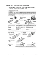
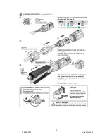
Page 11: ...46 805 201 Date 2017 09 26 Installing a power input connector on a power cable To install a Neutrik powerCON TRUE1 NAC3FX W input connector on a power Cable follow the original Neutrik instructions be...

Page 12: ...12 246 805 201 Date 2017 09 26...

Page 13: ...ed pair cable designed for RS 485 devices standard microphone cable cannot transmit control data reliably over long runs 24 AWG cable is suitable for runs up to 100 meters 328 ft Never use both a winc...

Page 14: ...to the wire conductors Do not apply AC mains power to the wire conductors at any other voltage than those specified in this manual Ratings for lifting wire Maximum voltage 240 V Maximum current 10 A...

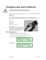
Page 15: ...ale 4 pole XLR connector Pin 1 and Pin 4 should be powered with 12 15 volt DC to enable the running of the motor Pin out Pin 1 GND Pin 2 NC Pin 3 NC Pin 4 12 15 volt DC Ready to use When the Winch 50...

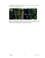
Page 16: ...or operation with without emergency stop Emergency stop disabled Emergency stop enabled When the emergency stop is enabled and the little piece of orange wire is not connected it is recommended that i...

Page 17: ...he local AC mains power voltage before applying power to the winch Do not apply AC mains power to the winch at any other voltage than that specified on the winch s serial number label Lifting cable co...

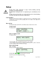
Page 18: ...rbalance before running with it This can be done by hanging some sort of weight in the wedge sleeve at the end of the wire Menu setting The menu structure is divided into two different areas for safer...

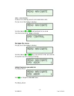
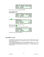
Page 19: ...buttons UP DOWN and hold them for 3 seconds Now the top line of the display is showing Navigate the menu The top line of the display is showing Push the buttons UP or DOWN to go up and down in the me...

Page 20: ...saved in the memory DMX ADDRESS setting The DMX address also known as the start channel is the first channel used to receive instructions from the controller For independent control each winch must be...

Page 21: ...annel 4 is used as an extra security channel The value on channel 4 needs to be between 50 and 55 for the motor to run All other values make the motor stop All other values will also reset any error s...

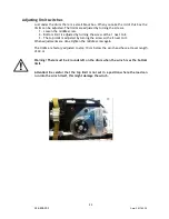
Page 22: ...the screw with a 1 next to it 3 The top limit is adjusted by turning the screw with a 2 next to it When adjustments are done tighten the middle screw again The limits are factory adjusted to stop 10 c...

Page 23: ...um 6 DMX channels TAC RANGE Tacho range Range 1 50 000 The tacho range is setting the maximum range of the Winch SPEED MAX Maximum speed Range 500 3 500 SPEED MAX sets the maximum speed If set to 1000...

Page 24: ...sition to the bottom position during the movement Synchronized movements of multiple winches If several winches are installed to perform synchronized movements the best result is achieved by using a f...

Page 25: ...e fuse in the winch is intact Winch will not start DMX lamp is blinking Check DMX signal The wire is not wound up on the drum correctly Manually lower the wire totally off the drum while controlling t...

Page 26: ...ompany The written result of the last inspection must be kept available at the site of operation e g by an inspection sticker on the winch showing the date of the inspection the basis of the inspectio...

Page 27: ...he product s lifetime Please contact Wahlberg Motion Design for details Life of the wire It is Wahlberg policy to apply the strictest possible calibration procedures and use the best quality materials...

Page 28: ...reased When there is evidence of severe corrosion like chain pitting When there is any evidence of internal corrosion in the rope This can be recognized by slackness of outer wires due to the internal...

Page 29: ...nd DMX channel 3 to 50 The wire loop is now running 1m down with 50 speed Emergency stop switch Only when emergency stop is enabled The emergency stop switch is connected to the female 4 pin XLR conne...

Reviews: