background image

4


DEU

Inhaltsverzeichnis

1. 

Zu Ihrer Sicherheit ...............................................................................................5

1.1 

Bestimmungsgemäßer Gebrauch ...............................................................5

1.2 Sicherheitshinweise ....................................................................................5
1.3 Warnstufen ..................................................................................................6

2. Montieren .............................................................................................................6

2.1  Standrohr montieren ...................................................................................6
2.2  Abdeckung entfernen ..................................................................................6
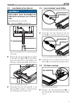
2.3  Leuchtenkopf montieren .............................................................................7
2.4  Leuchtenkopf anschließen ..........................................................................7
2.5  SD-Karte stecken .........................................................................................7
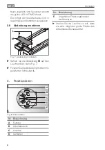
2.6  Abdeckung montieren .................................................................................8

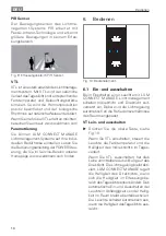
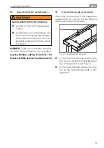
3. Positionieren ........................................................................................................8
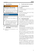
4. Anschließen .........................................................................................................9

4.1  Leuchte an Stromversorgung anschließen ..................................................9

5. 

Funktionen der Leuchte .......................................................................................9

5.1 Bedienfunktionen ........................................................................................9
5.2 Lichtmanagement .......................................................................................9

6. Bedienen ............................................................................................................ 10

6.1  Ein- und ausschalten ................................................................................. 10
6.2 Dimmen .................................................................................................... 11
6.3  Boost-Funktion aktivieren und deaktivieren .............................................. 11
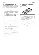
6.4  Lichtregelung kalibrieren ........................................................................... 12
6.5  LUM CONNECT MANAGE einstellen ....................................................... 12

7. 

Was tun, wenn? .................................................................................................13

8. 

Leuchtmittel wechseln .......................................................................................15

9. 

Leuchtenkopf justieren ......................................................................................15

10. Reinigen .............................................................................................................16
11. Reparieren ..........................................................................................................16
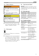
12. Demontieren ......................................................................................................17
13. Entsorgen ...........................................................................................................17
14. 

Technische Daten ...............................................................................................17

14.1 Abmessungen ........................................................................................... 17
14.2  Elektrische Werte ...................................................................................... 17
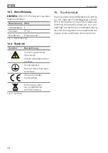
14.3 Klassifizierung ........................................................................................... 18
14.4 Symbole .................................................................................................... 18

15. Konformität ........................................................................................................18

Summary of Contents for 121820000-00801139

Page 1: ...Indirektleuchte Uplighter Luminaire indirect Apparecchio d illuminazione a luce indiretta LAVIGO VTL DPS Gebrauchsanweisung DEU Instructions For Use ENG Mode d emploi FRA Istruzioni per l uso ITA ...

Page 2: ...brand Highest product quality and a customer friendly service are the basis for the successful distribution of Waldmann products throughout the world If you want to make use of our service our service team can be reached at Service Hotline 49 0 77 20 6 01 170 Service E Mail service waldmann com Your Waldmann team FRA Bienvenue a Waldmann Nous aimerions vous remercier d avoir choisi un produit de l...

Page 3: ...lente qualità dei nostri prodotti ed il nostro servizio orientato ai clienti Nel caso in cui si desideri prendere contatto con il nostro servizio di assistenza il nostro team di assistenza è reperibile ai seguenti recapiti Servizio hotline 49 0 77 20 6 01 170 Servizio Email service waldmann com Il Suo team Waldmann Inhaltsverzeichnis 4 Table of Contents 19 Sommaire 34 Indice 49 ...

Page 4: ...e an Stromversorgung anschließen 9 5 Funktionen der Leuchte 9 5 1 Bedienfunktionen 9 5 2 Lichtmanagement 9 6 Bedienen 10 6 1 Ein und ausschalten 10 6 2 Dimmen 11 6 3 Boost Funktion aktivieren und deaktivieren 11 6 4 Lichtregelung kalibrieren 12 6 5 LUM CONNECT MANAGE einstellen 12 7 Was tun wenn 13 8 Leuchtmittel wechseln 15 9 Leuchtenkopf justieren 15 10 Reinigen 16 11 Reparieren 16 12 Demontiere...

Page 5: ...rbeiten an der Leuchte wie Montieren und Demontieren nur von einer Elektro Fachkraft durchführen lassen X X Netzspannung mit Nennspannung und Frequenz vergleichen die auf dem Leis tungsschild angegeben sind und sicher stellen dass sie identisch sind X X Leuchte erst an die Stromversorgung anschließen wenn die Leuchte vollstän dig montiert ist X X Leuchte an ein Versorgungsnetz mit Schutzleiter ans...

Page 6: ...können 2 Montieren WARNUNG Offenliegende elektrischeTeile Lebensgefahr durch Stromschlag X X Leuchte erst an die Stromversor gung anschließen wenn die Leuchte vollständig montiert ist X X Nur von einer Elektro Fachkraft durchführen lassen 2 1 Standrohr montieren VORSICHT Verletzungsgefahr durch kippende Leuchte Personen und Sachschaden X X Befestigungselemente ordnungs gemäß montieren X X Lesen Si...

Page 7: ...das Standrohr E siehe Fig 2 G F Fig 3 Leuchtenkopf fixieren X X Schrauben Sie die Schraube F in die Bohrung G im Tragarm und drehen Sie die Schraube fest siehe Fig 3 2 4 Leuchtenkopf anschließen I H Fig 4 Leuchtenkopf anschließen Teil 1 X X Verbinden Sie den Stecker I mit der Buchse H am Leuchtenkopf siehe Fig 4 K J Fig 5 Leuchtenkopf anschließen Teil 2 X X Verbinden Sie die Buchse J mit dem Steck...

Page 8: ...en X X Setzen Sie die Abdeckung M auf den Leuchtenkopf siehe Fig 7 X X Fixieren Sie die Abdeckung mit den mit gelieferten Schrauben L 3 Positionieren A C D B E Fig 8 Positionieren Nr Bezeichnung A Fenster B Arbeitsbereich C Leuchte D Sensoren Nr Bezeichnung E Ungefährer Erfassungsbereich der Sensoren X X Stellen Sie die Leuchte so auf dass sie eine möglichst große Fläche des Arbeitsbereichs beleuc...

Page 9: ... Sie das Indirekt licht mit voller Leistung betreiben 5 2 Lichtmanagement LUM CONNECT MANAGE Lichtmanage ment Systeme kombinieren Präsenz und Tageslichtsensoren Die Leuchte leuchtet nur wenn die Sensoren Anwesenheit im Raum registrieren und die Helligkeit des Tageslichts nicht ausreicht Funktionsweise Erkennt die Sensorik Anwesenheit in ihrem Erfassungsbereich und reicht die Hellig keit des Tagesl...

Page 10: ...e Bereich unserer Homepage www waldmann com finden 6 Bedienen Fig 10 Bedienelement 6 1 Ein und ausschalten Beim Einschalten einer Leuchte mit LUM CONNECT MANAGE Lichtmanagement schalten Indirektlicht und Direktlicht zeit versetzt ein Dabei wird die Lichtregelung automatisch an die Reflexionsverhältnisse des Raums angepasst VTL ein und ausschalten X X Drücken Sie die obere Taste siehe Fig 10 Wenn S...

Page 11: ...gkeit des Tageslichts ausreicht 6 2 Dimmen Indirektlicht dimmen HINWEIS Sie können das Indirektlicht bei dieser Leuchte nicht dimmen Direktlicht dimmen X X Drücken Sie die untereTaste und halten Sie dieseTaste gedrückt siehe Fig 10 Nach ungefähr einer Sekunde verändert die Leuchte ihre Helligkeit X X Um die Dimmrichtung zu wechseln drü cken Sie dieTaste erneut und halten Sie diese Taste gedrückt D...

Page 12: ...ühren dass die Leuchte auch bei aus reichender Helligkeit im Raum nicht automatisch ausschaltet X X Dimmen Sie die Leuchte bis der Arbeitsbereich mit der gewünschten Helligkeit beleuchtet wird Die eingestellte Helligkeit wird gespei chert Wenn sich die Helligkeit im Erfassungsbereich des Tageslichtsen sors ändert regelt LUM CONNECT MANAGE die Helligkeit der Leuchte sodass der Arbeitsbereich gleich...

Page 13: ... Warten Sie bis die Leuchte kons tant leuchtet Indirektlicht und Direktlicht schalten zeitversetzt ein Lichtregelung wird angepasst X X Warten Sie bis die Leuchte kons tant leuchtet Die Leuchte regelt die Farbtemperatur und die Beleuchtungs stärke des Indirekt lichts im Tagesverlauf nicht VTL ist ausgeschaltet X X Schalten Sie VTL ein siehe Kapi tel 6 1 Ein und ausschalten Seite 10 Speicherkarte f...

Page 14: ...ibrieren Seite 12 Leuchtenkopf ist nicht waagerecht ausge richtet Neigung des Leuch tenkopfs ist nicht opti mal eingestellt X X Justieren Sie den Leuchtenkopf siehe Kapitel 9 Leuchtenkopf jus tieren Seite 15 Anschlussleitung ist beschädigt Mechanische Ein wirkung auf die Anschlussleitung X X Beschädigte Anschlussleitung sofort von der Stromversorgung trennen und vom Hersteller von einem vom Herste...

Page 15: ...ollte ein Leuchtmittel ausfallen ist unser Service Team für Sie erreichbar Service Hotline 49 0 77 20 6 01 170 Service E Mail service waldmann com 9 Leuchtenkopf justieren Wenn der Leuchtenkopf nicht waagerecht ausgerichtet ist können Sie die Neigung des Leuchtenkopfs einstellen A Fig 12 Leuchtenkopf justieren X X Um den Leuchtenkopf anzuheben dre hen Sie die Justierschrauben A gegen den Uhrzeiger...

Page 16: ...ilden Reiniger 11 Reparieren WARNUNG Lebensgefahr durch Stromschlag X X Leuchte von der Stromversorgung trennen X X Reparaturen nur vom Hersteller von einem vom Hersteller beauf tragten Servicetechniker durchfüh ren lassen ACHTUNG Sachschaden durch unsachgemäße Reparatur Zerstörung oder Beschädigung der Leuchte X X Nur vom Hersteller freigegebene Ersatzteile verwenden HINWEIS Sollte ein Defekt an ...

Page 17: ...atlich bestimmten Stellen Mit einer ordnungsgemäßen Entsor gung vermeiden Sie mögliche negative Folgen für Mensch und Umwelt 14 Technische Daten HINWEIS Es gelten die Angaben auf dem Leistungsschild der Leuchte Das Leis tungsschild finden Sie auf der Abdeckung am Leuchtenkopf 14 1 Abmessungen Bezeichnung Wert Leuchtenkopf 1265 x 200 x 35 5 mm Leuchtenfuß 500 x 470 x 10 mm Gesamthöhe 2035 mm Tab 2 ...

Page 18: ...hr des elektrischen Schlags Schutzklasse I Betrieb mit Schutzleiter anschluss CE Konformitäts kennzeichen Entsorgung nach der europäischen WEEE Richtlinie Tab 5 Symbole 15 Konformität Hiermit erklärt HerbertWaldmann GmbH Co KG dass der Funkanlagentyp LAVIGO DPSinKombinationmitdemTALKModulder Richtlinie 2014 53 EU entspricht Der voll ständigeText der EU Konformitätserklärung ist unter der folgenden...

Page 19: ...ire to the power supply 24 5 Functions of the luminaire 24 5 1 Operating functions 24 5 2 Light management 24 6 Operation 25 6 1 Switching on and off 25 6 2 Dimming 26 6 3 Activating and deactivating the boost function 26 6 4 Calibration of the light control 27 6 5 Setting the LUM CONNECT MANAGE system 27 7 What to do if 28 8 Replacing the lamp 30 9 Adjusting the light head 30 10 Cleaning 31 11 Re...

Page 20: ... injuries and material damage X X Have the work at the luminaire such as mounting and dismounting performed only by a skilled electrician X X Compare the mains voltage with the nominal voltage and the frequency specified on the rating plate and make sure that they are identical X X Connect the luminaire to the power sup ply only when the luminaire has been completely assembled X X The luminaire mu...

Page 21: ...t hazards that may result in material damage in case of non obser vance 2 Mounting WARNING Exposed electric parts Danger of death due to electric shock X X Connect the luminaire to the power supply only when the luminaire has been completely assembled X X Have it performed by a skilled elec trician only 2 1 Mounting the column CAUTION Risk of injury caused by a tilting light Personal injury and ma...

Page 22: ...4 G F Fig 15 Fastening the light head X X Screw the screw F into the bore G in the support arm and tighten the screw see Fig 15 2 4 Connecting the light head I H Fig 16 Connecting the light head Part 1 X X Connect the plug I to the socket H at the light head see Fig 16 K J Fig 17 Connecting the light head Part 2 X X Connect the socket J to the plug K at the light head see Fig 17 2 5 Inserting the ...

Page 23: ...Place the cover M on the light head see Fig 19 X X Fasten the cover using the delivered screws L 3 Positioning A C D B E Fig 20 Positioning No Designation A Window B Work area C Luminaire D Sensors No Designation E Approximate detection range of the sensors X X Position the light such that the largest possible area of the work area is lit ...

Page 24: ... to operate the indi rect light at the maximum power 5 2 Light management LUM CONNECT MANAGE light manage ment systems combine presence and day light sensors The light is only switched on when the sensors detect the presence of a person in the room and the intensity of the daylight is insufficient Mode of operation If the sensors detect the presence of a per son in their detection range and the in...

Page 25: ...2 Operating element 6 1 Switching on and off When switching on a luminaire with the LUM CONNECT MANAGE light manage ment indirect light and direct light are switched on with a time delay The light con trol is adjusted automatically to the reflec tion conditions of the room Switching VTL on and off X X Press the upper switch see Fig 22 If you switchVTL on the luminaire con trols the colour temperat...

Page 26: ...he daylight is sufficient 6 2 Dimming Dimming the indirect light NOTE You cannot dim indirect light with this luminaire Dimming the direct light X X Press the lower switch and keep it depressed see Fig 22 After about one second the luminaire will change its brightness X X To change the dimming direction press the switch again and keep it depressed This will save the set brightness The next time th...

Page 27: ...ng switched off automati cally even if the light intensity in the room is sufficient X X Dim the luminaire until the work area is illuminated with the required brightness This will save the set brightness If the brightness in the detection range of the daylight sensor changes LUM CON NECT MANAGE adjusts the brightness of the luminaire such that the work area is illuminated homogeneously 6 5 Settin...

Page 28: ...the luminaire is lit per manently Indirect light and direct light are switched on with a time delay The light control is being adjusted X X Wait until the luminaire is lit per manently The luminaire does not control the col our temperature and the illuminance of the indirect light in the course of the day VTL is off X X Switch VTL on see chapter 7 1 Switching on and off page 30 Memory card is miss...

Page 29: ...ibrate the light control see chapter 6 4 Calibration of the light control page 27 The light head is not aligned horizontally Inclination of the light head is not adjusted optimally X X Adjust the light head see chap ter 9 Adjusting the light head page 30 The connecting cable is damaged Mechanical impact on the connecting cable X X Disconnect a damaged connect ing cable immediately from the power s...

Page 30: ...arable qualification only NOTE If a lamp should break down you can contact our service team Service Hotline 49 0 77 20 6 01 170 Service e mail service waldmann com 9 Adjusting the light head If the light head is not aligned horizon tally you can adjust the inclination of the light head A Fig 24 Adjusting the light head X X To lift the light head rotate the adjust ing screws A counterclockwise see ...

Page 31: ...th a cloth and a mild detergent 11 Repair WARNING Danger of death due to electric shock X X Disconnect the luminaire from the power supply X X Have repairs performed by the man ufacturer or by a service technician authorised by the manufacturer only NOTICE Material damage caused by improper repair Damage or destruction of the luminaire X X Use only spare parts approved by the manufacturer NOTE If ...

Page 32: ...sposal and desig nated by the authorities Proper disposal avoids adverse effects on man and the environment 14 Technical data NOTE The data given on the rating plate of the luminaire apply The rating plate can be found on the cover at the light head 14 1 Dimensions Designation Value Light head 1265 x 200 x 35 5 mm Base of the light 500 x 470 x 10 mm Total height 2035 mm Tab 2 Dimensions 14 2 Elect...

Page 33: ...electric shock Protection class I Operation with protec tive earth terminal CE conformity mark Disposal in accord ance with the European WEEE Directive Tab 5 Symbols 15 Conformity Hereby Herbert Waldmann GmbH Co KG declares that the radio equipment type LAVIGO DPS DPT together with the wire less module TALK module compliance with Directive 2014 53 EU The full text of the EU declaration of conformi...

Page 34: ...tion électrique 39 5 Fonctions du luminaire 39 5 1 Fonctions de commande 39 5 2 Gestion de la lumière 39 6 Utilisation 40 6 1 Allumer et éteindre 40 6 2 Faire varier l intensité de la lumière 41 6 3 Activation et désactivation de la fonction Boost 41 6 4 Calibrage de la régulation de la lumière 42 6 5 Régler le système LUM CONNECT MANAGE 42 7 Que faire si 43 8 Remplacer les lampes 45 9 Ajuster la ...

Page 35: ...propriée du luminaire et le travail incorrect sur celui ci peuvent entraî ner des blessures et des dommages maté riels X X Les travaux sur le luminaire comme le montage et le démontage doivent impé rativement être effectués par un élec tricien qualifié X X Comparer la tension du secteur avec la tension nominale et la fréquence indi quées sur la plaque signalétique et s as surer qu elles sont ident...

Page 36: ...ées ATTENTION Avertissement relatif à des dangers pouvant entraîner des blessures en cas de non ap plication des mesures indiquées AVIS Avertissement relatif à des dangers pouvant entraîner des dommages matériels en cas de non application des mesures indiquées 2 Montage AVERTISSEMENT Pièces électriques exposées Danger de mort par décharge électrique X X Ne raccorder le luminaire à l alimen tation ...

Page 37: ...enfoncez le bras de support entièrement dans le mât E voir Fig 2 G F Fig 3 Fixer la tête du luminaire X X Vissez la vis F dans l alésage G dans le bras support et serrez la vis à fond voir Fig 3 2 4 Raccorder la tête du lumi naire I H Fig 4 Raccorder la tête du luminaire par tie 1 X X Connectez la fiche I au connecteur femelle H de la tête du luminaire voir Fig 4 K J Fig 5 Raccorder la tête du lum...

Page 38: ...rement L M Fig 7 Monter le recouvrement X X Placez le recouvrement M sur la tête du luminaire voir Fig 7 X X Fixez le recouvrement à l aide des vis livrées L 3 Positionnement A C D B E Fig 8 Positionner le luminaire N Désignation A Fenêtre B Zone de travail C Luminaire N Désignation D Capteurs E Zone de détection approximative des capteurs X X Positionnez le luminaire de manière à éclairer une zon...

Page 39: ...stèmes de gestion de la lumière LUM CONNECT MANAGE combinent des capteurs de présence et des capteurs de lumière naturelle Le luminaire est allumé uniquement quand les capteurs détectent la présence de personnes dans la pièce et que la luminosité de la lumière naturelle est insuffisante Principe de fonctionnement Quand un capteur détecte la présence d une personne dans sa zone de détection et que ...

Page 40: ...e site www waldmann com 6 Utilisation Fig 10 Élément de commande 6 1 Allumer et éteindre Lors de la mise en marche d un luminaire doté de la gestion de la lumière LUM CONNECT MANAGE la commutation de la lumière indirecte et de la lumière directe se fait en différé La régulation de la lumière est alors adaptée automatiquement aux effets de réflexion de la pièce Allumer et éteindre VTL X X Appuyez s...

Page 41: ...osité de la lumière naturelle est suffisante 6 2 Faire varier l intensité de la lumière Varier l intensité de la lumière indirecte REMARQUE Avec ce luminaire il n est pas possible de varier l intensité de la lumière indirecte Faire varier l intensité de la lumière directe X X Appuyez sur la touche inférieure et tenez la appuyée voir Fig 10 Le luminaire modifie sa luminosité envi ron une seconde pl...

Page 42: ... un niveau élevé En conséquence il est possible que le luminaire ne s éteigne pas automati quement même si la luminosité dans la pièce est suffisante X X Réglez l intensité de la lumière du lumi naire jusqu à ce que la luminosité dans la zone de travail ait atteint le niveau requis La luminosité réglée est enregistrée Quand la luminosité change dans la zone de détection du capteur de lumière natur...

Page 43: ...ttendez jusqu à ce que le lumi naire reste allumé en continu La commutation de lumière indirecte et de la lumière directe se fait en différé La régulation de la lumière est adaptée X X Attendez jusqu à ce que le lumi naire reste allumé en continu Le luminaire ne régule pas la température de couleur et l inten sité lumineuse de la lumière indirecte au cours de la journée VLT est éteint X X Allumez ...

Page 44: ... régulation de la lumière page 42 La tête du luminaire n est pas alignée à l horizontale L inclinaison de la tête du luminaire n est pas réglée de manière optimale X X Ajustez la tête du luminaire voir chapitre 9 Ajuster la tête du lumi naire page 45 Le câble de raccor dement est endom magé Effet mécanique sur le câble de raccorde ment X X Séparer un câble de raccordement endommagé immédiatement d...

Page 45: ...nte vous pouvez contacter notre équipe du ser vice d après vente Ligne directe du service après vente 49 0 77 20 6 01 170 E mail du service après vente service waldmann com 9 Ajuster la tête du lumi naire Si la tête du luminaire n est pas alignée à l horizontale vous pouvez ajuster son incli naison A Fig 12 Ajuster la tête du luminaire X X Pour soulever la tête du luminaire tour nez les vis de rég...

Page 46: ...tion AVERTISSEMENT Danger de mort par décharge élec trique X X Déconnecter le luminaire de l ali mentation électrique X X Les réparations ne doivent être exé cutées que par le fabricant ou un technicien du service après vente mandaté par celui ci AVIS Dommages matériels dus à une répa ration non conforme Détérioration ou destruction du luminaire X X Seul l emploi de pièces de rechange agréées par ...

Page 47: ...autorités Une éli mination conforme aux prescriptions vous permet d éviter les effets néga tifs potentiels sur l Homme et l envi ronnement 14 Données techniques REMARQUE Les indications figurant sur la plaque signalétique du luminaire sont valables Vous trouverez la plaque signa létique sur le recouvrement de la tête du luminaire 14 1 Dimensions Désignation Valeur Tête du lumi naire 1265 x 200 x 3...

Page 48: ...e choc élec trique Classe de protection I Fonctionnement avec branchement du conducteur de protec tion Sigle de conformité CE Élimination selon la directive européenne DEEE Tab 5 Pictogrammes 15 Conformité Le soussigné HerbertWaldmann GmbH Co KG déclare que l équipement radioélec trique du type LAVIGO DPS DPT en combi naisonaveclemoduleradio TALKmoduleest conforme à la direvtive 2014 53 UE Le text...

Page 49: ...pparecchio d illuminazione all alimentazione elettrica 54 5 Funzioni dell apparecchio d illuminazione 54 5 1 Funzioni di comando 54 5 2 Gestione della luminosità 54 6 Comando 55 6 1 Accensione e spegnimento 55 6 2 Dimmerazione 56 6 3 Attivazione e disattivazione della funzione boost 56 6 4 Calibrazione della regolazione della luminosità 57 6 5 Regolazione di LUM CONNECT MANAGE 57 7 Cosa fare se 58...

Page 50: ...sioni e danni materiali X X Fare eseguire lavori sull apparecchio d il luminazione come montaggio e smon taggio solo da parte di un elettricista professionista X X Assicurarsi che la tensione di rete corri sponda alla tensione nominale e alla fre quenza indicate sulla targhetta X X Collegare l apparecchio d illuminazione all alimentazione elettrica solo una volta completamente montato X X Collegar...

Page 51: ...nza delle misure possono causare danni materiali 2 Montaggio AVVERTENZA Parti elettriche esposte Alta tensione pericolo di morte X X Collegare l apparecchio d illumina zione all alimentazione elettrica solo una volta completamente montato X X Fare eseguire solo da parte di un elettricista professionista 2 1 Montaggio del tubo verticale ATTENZIONE Il ribaltamento dell apparecchio d illu minazione p...

Page 52: ...erire il braccio di supporto completamente nel tubo ver ticale E vedi Fig 14 G F Fig 15 Fissaggio della testa dell apparec chio d illuminazione X X Avvitare la vite F nel foro G nel braccio di supporto e stringere la vite vedi Fig 15 2 4 Collegamento della testa dell apparecchio d illumina zione I H Fig 16 Collegamento della testa dell appa recchio d illuminazione parte 1 X X Collegare la spina I ...

Page 53: ... Fig 19 Montaggio della copertura X X Collocare la copertura M sulla testa dell apparecchio vedi Fig 19 X X Fissare la copertura mediante le viti L fornite in dotazione 3 Posizionamento A C D B E Fig 20 Posizionamento N Descrizione A Finestra B Area di lavoro C Apparecchio N Descrizione D Sensori E Campo d azione approssimativo dei sensori X X Posizionare l apparecchio d illumina zione in modo tal...

Page 54: ...ima potenza 5 2 Gestione della luminosità I sistemi di gestione della luminosità LUM CONNECT MANAGE combinano i sensori di presenza e i sensori di luce diurna L ap parecchio d illuminazione s illumina solo se i sensori registrano una presenza nella stanza e se la luminosità della luce diurna non è sufficiente Modo di funzionamento Se il sensore di presenza registra una pre senza nel suo campo d az...

Page 55: ...w waldmann com 6 Comando Fig 22 Elemento di comando 6 1 Accensione e spegnimento All accensione di un apparecchio d illumina zione mediante il sistema di gestione della luminosità LUM CONNECT MANAGE la luce indiretta e quella diretta si accendono con sfasatura temporale La regolazione della luminosità viene adeguata automati camente alle condizioni di riflessione della stanza Accensione e spegnime...

Page 56: ...zione si spegne automaticamente se la lumi nosità della luce diurna è sufficiente 6 2 Dimmerazione Dimmerazione della luce indiretta NOTA con questo apparecchio non è pos sibile dimmerare la luce indiretta Dimmerazione della luce diretta X X Premere il tasto inferiore e tenerlo pre muto vedi Fig 22 Dopo circa un secondo cambia la lumi nosità dell apparecchio d illuminazione X X Per cambiare la dir...

Page 57: ...illu minata con la luminosità desiderata La luminosità impostata viene salvata Se la luminosità nel campo d azione del sensore della luce diurna cambia LUM CONNECT MANAGE regola la lumino sità dell apparecchio d illuminazione in modo tale che la zona di lavoro venga sempre illuminata in modo omogeneo 6 5 Regolazione di LUM CON NECT MANAGE Regolazione di PIR sensore Fig 23 Sensori PIR X X Per orien...

Page 58: ...minosità viene con figurata X X Attendere finché l apparecchio è acceso in maniera costante La luce indiretta e quella diretta si accen dono con sfasatura temporale La regolazione della luminosità viene adat tata X X Attendere finché l apparecchio è acceso in maniera costante L apparecchio d illumi nazione non regola la temperatura del colore e l intensità d illumina zione della luce indi retta ne...

Page 59: ...rec chio non è orientata orizzontalmente L inclinazione della testa dell apparecchio d illuminazione non è regolata in modo otti male X X Regolare la testa dell apparec chio d illuminazione vedi capi tolo 9 Regolazione della testa dell apparecchio d illuminazione pagina 60 Il cavo di allaccia mento è danneggiato Effetto meccanico sul cavo di allacciamento X X Disinserire immediatamente l a limenta...

Page 60: ...on il nostro team di assistenza Linea telefonica dedicata di assistenza 49 0 77 20 6 01 170 E mail di assistenza service wald mann com 9 Regolazione della testa dell apparecchio d illumi nazione Se la testa dell apparecchio non è orientata orizzontalmente è possibile regolarne l in clinazione A Fig 24 Regolazione della testa dell apparec chio d illuminazione X X Per sollevare la testa dell apparec...

Page 61: ...a tensione pericolo di morte X X Scollegare l apparecchio d illumina zione dall alimentazione elettrica X X Le riparazioni devono essere ese guite solo dal costruttore o da un tecnico di assistenza autorizzato dal costruttore AVVISO Danni materiali dovuti a lavori di ripa razione eseguiti scorrettamente Danneggiamento o distruzione dell appa recchio d illuminazione X X Utilizzare esclusivamente le...

Page 62: ...nti di smaltimento auto rizzati Lo smaltimento regolare serve per evitare pericoli per l uomo e l am biente 14 Dati tecnici NOTA valgono le informazioni riportate sulla targhetta dell apparecchio d illumina zione La targhetta identificativa si trova sulla copertura della testa dell apparecchio 14 1 Dimensioni Descrizione Valore Testa dell appa recchio d illumi nazione 1265 x 200 x 35 5 mm Base del...

Page 63: ...tensione elettrica pericolosa Pericolo di folgorazione Classe di protezione I Funzionamento con conduttore di terra col legato Marcatura di confor mità CE Smaltimento secondo la direttiva europea WEEE RAEE Tab 10 Simboli 15 Conformità Il fabbricante Herbert Waldmann GmbH Co KG dichiara che il tipo di apparecchia tura radio LAVIGO DPS DPT in combina zione con il modulo radio TALK modulo è conforme ...

Page 64: ...5 457 810 00804223 nB 01 2019 TB Printed in Germany Änderungen vorbehalten 15 01 2019 Herbert Waldmann GmbH Co KG Peter Henlein Straße 5 D 78056 Villingen Schwenningen Telefon 49 0 77 20 601 0 Telefax 49 0 77 20 601 290 www waldmann com info waldmann com ...

Reviews: