background image

74

Istruzioni per l’uso  Apparecchio d'illuminazione a parete  DUW 2xx(D) 

"ATARO"

ITA

Montaggio parte 5 - Collegamento della testa dell’apparecchio

Dopo il collegamento

Vedi fig. 24.

r)  Posizionare  la  copertura  [24.4] 

nella  zona  di  collegamento  e 

farla scattare in arresto.

s)  Montare le due coperture late-

rali [24.5] alla barra di fissaggio 

[24.3].

t)  Montare la copertura dell'appa-

recchio [24.6] al chassis [24.1].

Fig. 22c 

(DUW 2xx

/D

)

Fig. 22a

Fig. 24

24.1

24.6

24.3

24.4

Fig. 22b 

(DUW 2xx)

24.5

 ! AVVERTENZA

Pericolo di lesioni

Se  non  vengono  usati  dispositivi 

di  fissaggio,  l'apparecchio  può 

cadere.


¾

Fissare la testa dell'apparecchio 

avvitando  le  due  viti  a  testa 

cilindrica con calotta [14.8] e le 

rosette di sicurezza [14.9] sotto 

la  testa  dell'apparecchio  (vedi 

fig. 14a).

Collegamento della testa 
dell'apparecchio 
d'illuminazione

Nota: 

Si raccomanda di piegare il 

cavo prima che il chassis venga in-

serito nella copertura (vedi fig. 23).

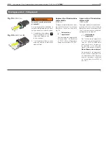
Vedi da fig. 22a fino a fig. 22c.

o)  Collegare il conduttore di terra 

(spina  piatta  a  manicotto)  alla 

testa dell'apparecchio (fig. 22a). 

p)  Collegare  mediante  spina  l'ali-

mentazione  domestica  e  la 

testa dell'apparecchio (Fig. 22b 

o 22c).

q)  Sistemare  i  cavi  nella  barra  di 

fissaggio [24.3].

Fig. 23

Summary of Contents for ATARO DUW 2 Series

Page 1: ...andleuchte Wall Mounted Uplighter Applique murale Apparecchio d illuminazione a parete ATARO DUW 2xx DUW 2xx D DEU Gebrauchsanweisung ENG Instructions For Use FRA Mode d emploi ITA Istruzioni per l us...

Page 2: ...2 Fig 1 DUW 2xx D ATARO DUW 214 Translations Original DEU Gebrauchsanweisung 4 ENG Instructions For Use 24 FRA Mode d emploi 44 ITA Istruzioni per l uso 64...

Page 3: ...3 Fig 2 DUW 221 2 6 2 3 2 5 2 1 2 4 DUW 2xx D ATARO Fig 3b DUW 2xx D Fig 3a DUW 2xx 2 2 DUW 2xx D ATARO...

Page 4: ...r eine gute Wahl getroffen denn das Haus Waldmann ist stets bem ht seinen Kunden nur ausgereifte und zuverl s sige Produkte zu liefern F r das uns entgegengebrachte Vertrauen bedanken wir uns hiermit...

Page 5: ...kennzeichnet Punkte die bei Missachtung oder falscher Handhabung zu Verlet zungen oder Sachbesch digung f hren k nnen ACHTUNG Dieses Symbol kennzeichnet Punkte die bei Missachtung oder falscher Handh...

Page 6: ...h unzureichen de Befestigung Bei unsachgem er Montage kann die Leuchte herunterfallen Montage nur mittels geeigneter Schrauben und D bel Montage nur an einer zur Mon tage geeigneten Wand Montage nur d...

Page 7: ...r durch hei e Oberfl che Das Ber hren des Leucht mittels bei eingeschalteter Leuchte oder einige Zeit danach kann zu schweren Verbrennungen f hren Vor Wartungs und Reparatur arbeiten die Lampe abk hle...

Page 8: ...n Stromverbrauch Die DUW R misst und regelt automatisch das Licht in ihrer Umgebung Bei einfallendem Sonnenlicht wird nur wenig oder gar kein zus tzliches Licht abgegeben Bei wenig einfallendem Licht...

Page 9: ...rieb VDE Zulassung CE Konformit tskennzeichen ENEC Zulassung SEV Zulassung Zweckbestimmung Der Hersteller kann nicht f r Sch den verantwortlich gemacht werden die infolge der Nutzung abweichend vom be...

Page 10: ...enabdeckung durch Anheben in der Mitte WARNUNG Warnung vor herunterfallender Leuchte Bei unsachgem er Montage kann die Leuchte herunterfallen Montage nur mittels geeigneter Schrauben und D bel Montage...

Page 11: ...Zum Bedienen der dimmbaren Leuchten z B DUW 228 D sind abh ngig vom eingebau tenVorschaltger t unterschied liche Bedienger te erforderlich Verwenden Sie keinen Dim mer Standardm ig sind die Leuch ten...

Page 12: ...tigungsschiene eindre hen g Schrauben 15 5 auf beiden Seiten soweit herausdrehen bis die Blende 14 2 die ge w nschte Position einnimmt h Position mit Wasserwaage pr fen und ggf nochmals kor rigieren F...

Page 13: ...ng l st n Den zugeh rigen unteren Rast haken nach hinten b dr cken und das Chassis aus dem Blen denrahmen herausnehmen Einsetzen des Leuchtenchassis Siehe Fig 16 j Chassis 16 1 von oben in den Blenden...

Page 14: ...Verletzungsgefahr Bei fehlender Sicherung kann die Leuchte herunterfallen Leuchtenkopf durch festschrau ben der beiden Linsenkopf schrauben 14 8 und Siche rungsscheiben 14 9 unter dem Leuchtenkopf fix...

Page 15: ...te Lichtausbeute und eine maximale Lebensdauer erreicht ACHTUNG Besch digung durch falsche Anschlussspannung Eine falsche Anschlussspannung kann zur Besch digung oder Zer st rung der Leuchte f hren Vo...

Page 16: ...icherweise ber externe Schal ter ein und ausgeschaltet Dimmbare Leuchte DUW 2xx D Zum Bedienen von digital dimm baren Leuchten z B DUW 228 D ist die Verwendung eines Tast schalters notwendig siehe An...

Page 17: ...D ATARO DEU die Lampen nicht synchron dimmen Nur g ltig bei dimmbaren Leuchten z B DUW 228 D Zum Synchronisieren von ungleich dimmenden Lampen sind folgende Schritte auszuf hren a Taster lang dr cken...

Page 18: ...g 40 a Lampe abk hlen lassen b Trennen Sie die Leuchte vom Netz Ausschalten c Nehmen Sie die Lampenabde ckung ab d Drehen Sie die Lampe 40 2 um ca 90 nach rechts a und nehmen Sie diese nach oben herau...

Page 19: ...inigung der Leuchtenteile nur mit normalem Haushaltsreini ger getr nkten Tuch Vertr glichkeit der verwendeten Mittel mit Lacken und Kunst stoffen beachten ACHTUNG Umweltgef hrdung Falsche Entsorgung g...

Page 20: ...x 240 x 50 5 mm Gebrauchsanweisung Wandleuchte DUW 2xx D ATARO DEU Allgemein Klassifizierung Schutzart IP20 Schutzklasse I Betriebsart Dauerbetrieb Technische Sicherheitspr fung entsprechend EN 60598...

Page 21: ...nahme ca 113 W Leistungsfaktor 0 99 Best ckung 2 x T16 54 W Leuchtstofflampen Elektronisches Vorschaltger t Abmessungen ca 1220 x 240 x 50 5 mm ACHTUNG Gefahr der Besch digung durch Abweichungen von d...

Page 22: ...22 Anhang 1 Schaltbilder Fig 51b Leuchte DUW 2xx D Bedienung ber DALI Bus Fig 51a Leuchte DUW 2xx D Bedienung ber externen Tastschalter Gebrauchsanweisung Wandleuchte DUW 2xx D ATARO DEU...

Page 23: ...Anhang 2 Bohrplan Fig 60 Leuchte a b c d e f g1 g2 g3 g4 g5 g6 g7 DUW 214 DUW 224 620 530 45 85 360 82 5 310 420 530 DUW 221 DUW 239 920 830 45 115 330 600 102 5 460 580 700 820 DUW 228 DUW 254 1220...

Page 24: ...Waldmann product And you have surely made a good choice because Waldmann always endeavours to supply perfectly designed and reliable products We thank you for your trust in our products and hope that...

Page 25: ...ge in case of non observ ance or wrong handling NOTICE This symbol identifies items that may result in material damage in case of non observance or wrong handling DANGER Danger caused by wrong mountin...

Page 26: ...the light may fall down Mounting with suitable screws and dowels only Mounting to a wall suitable for mounting only Mounting by a skilled electri cian only DANGER Explosion hazard Operating the light...

Page 27: ...as spare parts CAUTION Risk of burns caused by hot surface Touching the lamp with the light switched on or some time afterwards may result in seri ous burns Allow the lamp to cool down before carryin...

Page 28: ...reover this light reduces the power consumption The DUW R measures the surrounding light and adjusts the light intensity accordingly In the case of incident sunlight very little additional light if an...

Page 29: ...ent operation VDE approval CE Conformity mark ENEC approval SEV approval Designation of purpose The manufacturer cannot be held liable for damage caused by using the unit for purposes contrary to the...

Page 30: ...lamp cover for it by lifting it in its centre WARNING Warning against the light falling down When mounted incorrectly the light may fall down Mounting with suitable screws and dowels only Mounting to...

Page 31: ...rcuit diagram on page 42 Important information The operation of the dimmable lights e g DWP 228 D re quires different operating units depending on the mounted bal last unit Never use a dimmer As stand...

Page 32: ...14 3 Note The cover 14 2 must be aligned to the fastening rail 14 3 the left and right over laps k must be identical Adjusting the light head See Fig 15 If required the angle between light head and wa...

Page 33: ...back a and lift the chassis until it comes loose n Press the associated lower detent hook toward the back b and remove the chassis from the cover frame Inserting the light chassis See Fig 16 j Insert...

Page 34: ...Fig 22b DUW 2xx 24 5 WARNING Risk of injury When not secured the uplighter may fall down Tighten both oval head screws 14 8 and circlips 14 9 at the underside of the light head to fasten it see Fig 1...

Page 35: ...ontrol during the first days or weeks results in an increased brightness and in maximum use ful life NOTICE Damage caused by wrong mains voltage A wrong mains voltage may dam age or destroy the light...

Page 36: ...usu ally switched on off via an external switch Dimmable light DUW 2xx D The operation of digitally dimmable lights e g DUW 228 D requires the use of a touch switch see Connection Press briefly 0 5 s...

Page 37: ...rer the lamps are not dimmed synchronously Only applicable to dimmable lights e g DUW 228 D If the lamps do not dim in the same way carry out the following steps for synchronising a Press the switch l...

Page 38: ...be used as spare parts Replacing the lamp Please also observe Fig 40 a Let lamp cool down b Disconnect the light from the mains switch off c Remove the lamp cover d Turn the lamp 40 2 by approx 90 to...

Page 39: ...rvals Clean the light parts with a cloth impregnated with a suitable household cleaning agent only Make sure the agents used are compatible with paints and plastics NOTICE Environmental hazard Wrong d...

Page 40: ...lamps Electronic ballast unit Dimensions approx 920 x 240 x 50 5 mm General Classification Protection type IP 20 Protection class I Operating mode Continuous operation Technical safety check according...

Page 41: ...D Rated voltage 220 240 V AC Frequency range 50 60 Hz Power consumption approx 113 W Power factor 0 99 Fitted with 2 x T16 54 W fluorescent lamps Electronic ballast unit Dimensions approx 1220 x 240...

Page 42: ...42 Instructions For Use Wall Mounted Uplighter DUW 2xx D ATARO ENG Annex 1 Circuit diagrams Fig 51b Light DUW 2xx D Operation via DALI bus Fig 51a Light DUW 2xx D Operation via external touch switch...

Page 43: ...RO ENG Annex 2 Hole pattern Fig 60 Light a b c d e f g1 g2 g3 g4 g5 g6 g7 DUW 214 DUW 224 620 530 45 85 360 82 5 310 420 530 DUW 221 DUW 239 920 830 45 115 330 600 102 5 460 580 700 820 DUW 228 DUW 25...

Page 44: ...s avez sans aucun doute fait le bon choix car l entreprise Waldmann fait tout son possible pour proposer ses clients uniquement des produits bien tudi s et dignes de confiance Nous vous remercions pou...

Page 45: ...rrecte entra ner des blessures ou des dommages mat riels AVIS Ce symbole mat rialise les points pouvant en cas de non respect ou de manipulation incorrecte entra ner des dommages mat riels DANGER L ut...

Page 46: ...s t ef fectu correctement il est possible que le bo tier du luminaire soit sous tension lectrique Le conducteur de pro tection doit tre reli au bo tier du luminaire Le branchement doit tre r a lis exc...

Page 47: ...entra ner des blessures graves ou mortelles D connecter le luminaire du secteur avant toute op ration de maintenance ou de r pa ration Les travaux de maintenance et de r paration ne doivent tre r ali...

Page 48: ...ailleurs ce luminaire r duit la consommation en courant La version DUW R mesure et r gle automatiquement la lumi re dans la pi ce o vous vous trouvez En cas de lumi re du jour incidente peu ou pas de...

Page 49: ...igle de conformit CE Homologation ENEC Homologation SEV Utilisation pr vue Le fabricant d cline toute responsabilit concernant les dommages qui r sulteraient d une utilisation non conforme l emploi pr...

Page 50: ...centre AVERTISSEMENT Mise en garde contre la chute du luminaire Le luminaire peut tomber si le montage n a pas t r alis cor rectement Proc der au montage unique ment l aide de vis et de che villes app...

Page 51: ...nformation importante Diff rents appareils de com mande sont requis en fonction du ballast lectronique int gr pour la commande des lumi naires variateur de lumi re par ex DUW 228 D Ne pas utiliser de...

Page 52: ...oit tre align sur le rail de fixation 14 3 saillie k identique gauche et droite du rail Ajustage de la t te du luminaire Voir Fig 15 Si n cessaire vous pouvez mo difier l angle entre la t te du lu min...

Page 53: ...e de sa fixation n Appuyer vers l arri re sur les deux crochets inf rieurs corres pondants b et retirer le ch ssis du cadre de protection Mise en place du ch ssis du luminaire Voir Fig 16 j Ins rer le...

Page 54: ...AVERTISSEMENT Danger de blessures Le luminaire peut tomber en cas de protection d fectueuse Fixer la t te du luminaire en ser rant les deux vis t te goutte de suif 14 8 et les rondelles de protection...

Page 55: ...es semaines permet d obtenir un meilleur rendement lumineux et une dur e de vie maximale AVIS D t rioration en raison d une ten sion de branchement erron e Une tension d alimentation in correcte peut...

Page 56: ...Un bouton poussoir est n cessaire pour utiliser les luminaires varia teur de lumi re digital par ex DUW 228 D voir Raccordement Br ve activation 0 5 s MARCHE ARR T Longue activation 0 5 s variation d...

Page 57: ...synchrone Valable uniquement pour les lumi naires variateur de lumi re par ex DUW 228 D Effectuer les tapes suivantes pour synchroniser des tubes variation de lumi re diff rente a Longue activation du...

Page 58: ...abricant est autoris Remplacement des tubes Observez galement la Fig 40 a Laisser refroidir le tube b D connecter le luminaire l teindre c Enlever le recouvrement du tube d Tourner le tube 40 2 d env...

Page 59: ...des l ments du luminaire uniquement avec un chiffon imbib d un produit m nager usuel S assurer que les produits utili s s sont compatibles avec les laques et les plastiques AVIS Danger pour l environn...

Page 60: ...Ballast lectronique Dimensions env 920 x 240 x 50 5 mm G n ralit s Classification Indice de protection IP20 Classe de protection I Mode de fonctionnement Fonctionnement continu Contr le technique de...

Page 61: ...Gamme de fr quence 50 60 Hz Consommation env 113 W Facteur de puissance 0 99 quipement 2 x T16 54 W tubes fluorescents Ballast lectronique Dimensions ennv 1220 x 240 x 50 5 mm AVIS Risque d endommage...

Page 62: ...2 Mode d emploi applique murale DUW 2xx D ATARO FRA Annexe 1 Sch mas de connexions Fig 51b Luminaire DUW 2xx D Commande par bus DALI Fig 51a Luminaire DUW 2xx D Commande par un bouton poussoir externe...

Page 63: ...e 2 Sch ma de per age Fig 60 Luminaire a b c d e f g1 g2 g3 g4 g5 g6 g7 DUW 214 DUW 224 620 530 45 85 360 82 5 310 420 530 DUW 221 DUW 239 920 830 45 115 330 600 102 5 460 580 700 820 DUW 228 DUW 254...

Page 64: ...ldmann Pu essere certo di avere fatto una buona scelta perch Waldmann si impegna sempre ad offrire ai propri clienti solo prodotti completi ed affidabili Vi ringraziamo per la fiducia dataci e speriam...

Page 65: ...danni materiali AVVISO Questo simbolo indica i punti che in caso di inosservanza o di uso inadatto possono provocare danni materiali PERICOLO Pericolo dovuto al montaggio errato o all uso inadatto Il...

Page 66: ...dovuto a un fissaggio insufficiente Se montato in modo errato l appa recchio pu cadere Per il montaggio si devono uti lizzare solo viti e tasselli adatti Il montaggio va eseguito solo ad una parete a...

Page 67: ...ti Toccare la lampada fluore scente quando accesa o poco dopo averla spenta pu comportare gravi ustioni Prima di effettuare le operazioni di manutenzione e riparazione lasciare raffreddare la lampada...

Page 68: ...l uso Quest apparecchio d illuminazione consuma inoltre meno corrente Il modello DUW R misura e regola automaticamente la luce dell ambiente In presenza di forte luce solare l apparecchio emette solo...

Page 69: ...epito per il funzionamento continuo Omologazione VDE Contrassegno di conformit CE Omologazione ENEC Omologazione SEV Impiego conforme allo scopo previsto Il costruttore non si assume la responsabilit...

Page 70: ...fine togliere la copertura dell apparecchio d illuminazione sollevando la sua parte centrale AVVERTENZA Pericolo di caduta dell apparecchio Se montato in modo errato l appa recchio pu cadere Per il mo...

Page 71: ...ervare anche lo schema di collegamento a pagina 82 Informazione importante Per l utilizzo degli apparecchi d illuminazione dimmerabili per es DUW 228 D sono necessari diversi dispositivi di comando in...

Page 72: ...eata rispetto alla barra di fissaggio 14 3 deve sporgere a sinistra e a destra k in modo omogeneo Regolazione della testa dell apparecchio d illuminazione Vedi fig 15 In caso di necessit pu essere mod...

Page 73: ...e sollevare il chassis finch si stacchi n Premere il rispettivo gancio ad incastro inferiore verso il lato posteriore b e rimuovere il chassis dal telaio della copertura Inserimento del chassis Vedi...

Page 74: ...di lesioni Se non vengono usati dispositivi di fissaggio l apparecchio pu cadere Fissare la testa dell apparecchio avvitando le due viti a testa cilindrica con calotta 14 8 e le rosette di sicurezza 1...

Page 75: ...le prime settimane si ottiene una resa di luce maggiore e una durata utile massima AVVISO Danni dovuti a una tensione di collegamento errata Una tensione di collegamento erra ta pu danneggiare o distr...

Page 76: ...i e disinseriti tramite interruttori esterni Apparecchio d illuminazione dimmerabile DUW 2xx D Perilcomandodiapparecchidimmera bilidigitalmente peres DUW228 D necessario usare un interruttore a tasto...

Page 77: ...truttore le lampade non dimme erano in modo sincrono Valido solo per gli apparecchi d il luminazione dimmerabili per es DUW 228 D Per sincronizzare lampade con dimmerazione diversa bisogna eseguire le...

Page 78: ...zione della lampada Osservare anche la fig 40 a Fare raffreddare la lampada fluorescente b Staccare l apparecchio d illumi nazione dalla corrente spegni mento c Togliere la copertura della lam pada d...

Page 79: ...ell apparecchio d illuminazione utilizzare solo un panno imbe vuto di normale detergente per uso domestico Assicurarsi che i prodotti uti lizzati siano compatibili con le vernici e con i materiali sin...

Page 80: ...mentatore elettronico Dimensioni ca 920 x 240 x 50 5 mm Note generali Classificazione Grado di protezione IP20 Classe di protezione I Modo di funzionamento funzionamento continuo Controllo tecnico del...

Page 81: ...ale 220 240 V AC Gamma di frequenza 50 60 Hz Potenza assorbita circa 113 W Fattore di potenza 0 99 Dotazione 2 x T16 54 W lampade fluorescentii Alimentatore elettronico Dimensioni ca 1220 x 240 x 50 5...

Page 82: ...illuminazione a parete DUW 2xx D ATARO ITA Appendice 1 Schemi elettrici Fig 51b Apparecchio d illuminazione DUW 2xx D Comando mediante bus DALI Fig 51a Apparecchio d illuminazione DUW 2xx D Comando m...

Page 83: ...pendice 2 Schema di foratura Fig 60 Apparecchio d illuminazione a b c d e f g1 g2 g3 g4 g5 g6 g7 DUW 214 DUW 224 620 530 45 85 360 82 5 310 420 530 DUW 221 DUW 239 920 830 45 115 330 600 102 5 460 580...

Page 84: ...84 Best Nr 405 317 810 copyright H Waldmann GmbH Co KG nB 06 2011 TB nderungen vorbehalten Printed in Germany Ausgabe 09 06 2011 DUW 2xx D ATARO...

Reviews: