background image

15 

Installation


Gas Connection 

NOTE:  ALL GAS FITTING MUST ONLY BE CARRIED OUT BY A QUALIFIED PERSON. 


1. Waldorf Cooktops do not require electrical connection, as they function totally on the gas supply. 
2. 

It is essential that gas supply is correct for Cooktop being installed and that adequate supply 

pressure and volume are available.  The following checks should be made before installation:- 

a.  Gas Type the appliance has been supplied for is shown on a coloured stickers located above gas 

entry point and on rating plate.  Check that this is correct for gas supply the appliance is being 

installed for.  Gas conversion procedure is detailed in this manual. 

b.  Supply Pressure required for this appliance is shown in ‘Specifications’ section of this manual.  

Check gas supply to ensure that adequate supply pressure exists. 

c.  Input Rate of this appliance is shown on Rating Plate and in ‘Specifications’ section of this 

manual.  Input rate should be checked against available gas supply line capacity.  Particular 

note should be taken if appliance is being added to an existing installation. 


NOTE:  It is important that adequately sized piping runs directly to connection joint on appliance 

with as few tees and elbows as possible, to give maximum supply volume. 


3. 

Fit gas regulator supplied, into gas supply line as close to appliance as possible. 


NOTE:  Gas pressure regulator provided with this appliance is convertible between Natural Gas and 

LPG as per ‘Gas Conversion Section’ in this manual. 


Ensure regulator is converted to correct gas type that appliance will operate on. 


Regulator outlet pressure is fixed ex-factory for gas type that regulator is converted to and it 
is NOT to be adjusted. 


For RN8200G-B and RN8203G-B models, 

regulator connection is ½" BSP female.  Connection 

on the unit is ½" BSP male. 

For RN8400G / RN8600G / RN8800G, regulator connections are ¾" BSP female.  Connection 

on unit is ¾" BSP male. 
(Refer to ‘Specifications’ section for gas supply location dimensions). 


NOTE:  A Manual Isolation Valve must be fitted to the individual appliance supply line. 


4. 

Correctly locate appliance into its final operating position and using a spirit level, adjust legs so that 

appliance is level and at correct height. 

5. 

Connect gas supply to appliance.  A suitable joining compound which resists breakdown action of 

LPG must be used on every gas line connection, unless compression fittings are used. 

6. Check all gas connections for leakages using soapy water or other gas detecting equipment. 

7. Check gas operating pressure is as shown in ‘Specifications’ section. 

 
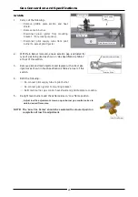
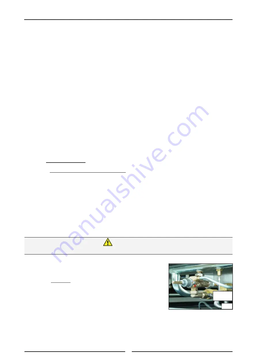
NOTE:  Operating pressure is to be measured at manifold test point 

with 2 burners operating at ‘High Flame’ setting. 


8. 

Verify operating pressure remains correct. 


NOTE:  This  appliance  is  fitted  with  adjustable  feet  to  enable  appliance  to  be  positioned  securely 

and level.  This should be carried out on completion of gas connection. 

M a n i f o l d 
Test Point 

Fig 3 


D

O


NOT


USE


A


NAKED


FLAME


TO


CHECK


FOR


GAS


LEAKAGES

Warning 

Summary of Contents for RNB8200G

Page 1: ...n u a l Gas Cooktops Series RN8200G RNL8200G RNB8200G RNLB8200G RN8400G RNL8400G RNB8400G RNLB8400G RN8600G RNL8600G RNB8600G RNLB8600G RN8800G RNL8800G RNB8800G RNLB8800G Date Purchased Serial Number Dealer Service Provider 228605 26 For use in GB IE DK ...

Page 2: ... Service tel 800 263 1455 Toll Free NEW ZEALAND Moffat Limited Web www moffat co nz E Mail sales moffat co nz Main Office tel 0800 663328 UNITED KINGDOM Blue Seal Web www blue seal co uk E Mail sales blue seal co uk Sales tel 44 121 327 5575 fax 44 121 327 9711 Spares tel 44 121 322 6640 fax 44 121 327 9201 Service tel 44 121 322 6644 fax 44 121 327 6257 UNITED STATES Moffat Web www moffat com Sal...

Page 3: ...cation Clearances Assembly Fitting Adjustable Feet Rear Rollers to Leg Stand Units Fitting Adjustable Feet Rear Rollers to Cabinet and Refrigeration Bases Gas Connection Commissioning Operation 17 Operation Guide Description of Controls Open Burners F Flame Failure Option Open Burners PF Pilot and Flame Failure Option Griddle Cleaning and Maintenance 20 Before Commencing Cleaning Open Burner Clean...

Page 4: ...NCE MUST NOT BE LEFT ON UNATTENDED IT IS RECOMMENDED THAT A REGULAR INSPECTION IS MADE BY A COMPETENT SERVICE PERSON TO ENSURE CORRECT AND SAFE OPERATION OF YOUR APPLIANCE IS MAINTAINED DO NOT STORE OR USE GASOLINE OR OTHER FLAMMABLE VAPOURS OR LIQUIDS IN THE VICINITY OF THIS OR ANY OTHER APPLIANCE DO NOT SPRAY AEROSOLS IN THE VICINITY OF THIS APPLIANCE WHILE IT IS IN OPERATION Warning This applia...

Page 5: ...ld Front LB Low Back and Bold Front 2 Open Burner Options F With Flame Failure Protection PF With Pilot and Flame Failure Protection 3 Base Stand Options B Bench Mount CB Cabinet Base excluding RN8200G Series LS Leg Stand excluding RN8200G Series RB Refrigerated Base RN8600G and RN8800G Series only General A heavy duty high efficiency Cooktop for modular kitchens It has a high option Cooktop Gridd...

Page 6: ...See Gas Connection information overleaf Natural Gas LP Gas Input Rate N H G C each Open Burner 28 MJ hr 28 MJ hr each 300mm Griddle Section 21 MJ hr 21 MJ hr Supply Pressure 1 13 3 40 kPa 2 75 4 50 kPa Burner Operating Pressure 0 95 kPa 2 6 kPa Gas Connection See Gas Connection information overleaf Natural Gas G20 Propane G31 Open Burner each Griddle each 300mm section Open Burner each Griddle eac...

Page 7: ...oor 55mm for bench top B models and is reached from beneath appliance Refer to Dimensions section With exception of RN8200G B and RN8203G B models which are 100mm from right hand side 32mm from rear and 70mm from floor Connection is BSP male thread for RN8200G and RN8203G models Connection is BSP male thread for all other models Natural Gas Town Gas Input Rate N H G C each Open Burner 28 MJ hr 28 ...

Page 8: ...6 Dimensions Bench Models Refer to Page 9 for Cooktop options Rating Plate Location for this option R RN L 8400G B RN L 8200G B R RN L 8600G B RN L 8800G B ...

Page 9: ... Dimensions Cabinet Base Models RN8200G Models not available in Cabinet Base option RN L 8400G CB RN L 8600G CB R Rating Plate Location for this option R RN L 8800G CB Refer to Page 9 for Cooktop options ...

Page 10: ... Dimensions Leg Stand Models RN8200G Models not available in Leg Stand Base option RN L 8400G LS Refer to Page 9 for Cooktop options Rating Plate Location for this option R R RN L 8600G LS RN L 8800G LS ...

Page 11: ...ensions Refrigerated Base Models RN8200G and RN8400G Models not available in Refrigerated Base option RN L 8600G RB RN L 8800G RB Refer to Page 9 for Cooktop options Rating Plate Location for this option R R ...

Page 12: ...e only available in Bench Model B option RN8400G models are available in Bench Model B Cabinet Base CB or Leg Stand LS model options RN8600G and RN8800G are available in Bench Model B Cabinet Base CB Leg Stand LS or Refrigeration Base RB model options For Refrigeration Cabinet Specifications and Dimensions refer to Refrigeration Cabinet Installation and Operation Manual supplied with appliance ...

Page 13: ...sed service agent They are not to be adjusted by the installation person Unpacking Remove all packaging and transit protection from appliance including all protective plastic coating from exterior stainless steel panels Check equipment and parts for damage Report any damage immediately to the carrier and distributor Report any deficiencies to distributor who supplied appliance Check available gas ...

Page 14: ...hat all feet are fitted 2 Adjust the four feet to make Cooktop steady and level Fitting of Adjustable Feet Rear Rollers to Leg Stand Units 1 Remove all pot stands pot stands supports burner caps burner bowls griddle plates and other removable items 2 Lower cooktop onto its rear face 3 Attach four cooktop legs to leg mount points on underside of cooktop unit 4 Secure each leg hand tight 5 Align 4 r...

Page 15: ...eg housings to secure rear of base tray to rear cooktop legs and tighten up bolts using a 24mm socket b Fit rear rollers to rear leg supports c Secure rear rollers to rear leg supports using locating screw supplied d Tighten screw using a 10mm spanner 9 Lift cooktop back onto its legs rollers and refit all griddle plates open burners trivets and pot stands 10 Adjust adjustable feet to level applia...

Page 16: ...liance back to floor and adjust adjustable feet to level appliance Rear Rollers fitting 1 Raise appliance from floor by approximately 75 mm using suitable lifting equipment i e Palletiser Forklift to allow rear adjustable feet to be removed 2 Unscrew and remove both rear adjustable feet from rear leg housings 3 Fit rear roller to rear leg housing and align screw hole in side of rear leg housing wi...

Page 17: ...h this appliance is convertible between Natural Gas and LPG as per Gas Conversion Section in this manual Ensure regulator is converted to correct gas type that appliance will operate on Regulator outlet pressure is fixed ex factory for gas type that regulator is converted to and it is NOT to be adjusted For RN8200G B and RN8203G B models regulator connection is BSP female Connection on the unit is...

Page 18: ...ecord of Date of Purchase Date of Installation and Serial Number of Appliance recorded and kept with this manual These details can be found on the Rating Plate For Bench Cabinet Base and Leg Stand Models Rating Plate is attached to underside of right hand side front Cooktop lower trim For the Refrigerated Base Model Rating Plate is located inside right hand front panel and can be viewed through up...

Page 19: ... on Gas Control Knob Griddle Options will also have a piezo igniter fitted Open burner control knobs with Flame Failure Option Only will only have Off Low Flame and High Flame positions Griddle Open Burners with PF Option fitted Burner Control OFF Position PILOT Burner HIGH Flame LOW Flame Gas Control Knobs Piezo Igniter Griddles Only Open Burner F Option Only OFF Position HIGH Flame LOW Flame Rea...

Page 20: ...nually re light burner each time that it is turned ON as burner will automatically light itself off the pilot burner Flame Failure Protection is incorporated for each burner by way of a thermo electric system which will shut off gas supply to that burner in the event that burner goes out so that un burnt gas is not expelled a Select burner required depress and turn the gas control knob anti clockw...

Page 21: ...lly anti clockwise to Low Flame position g When main burner is not required depress and turn gas control knob clockwise back to OFF position Turning OFF the Griddle Burner Pilot a To turn OFF griddle but keep pilot burner alight rotate gas control knob to PILOT position Griddle burner will extinguish and pilot will remain alight b To turn OFF PILOT depress and turn gas control knob clockwise back ...

Page 22: ...To keep your Cooktop clean and operating at peak efficiency follow the procedures shown overleaf Always turn off the gas electrical supply before cleaning the appliance This appliance is not water proof Do not use water jet spray to clean interior or exterior of this appliance Caution Burner Body Griddle Plate Grease Tray Spill Tray Pot Stand Burner Cap Burner Mounting Rail For Refrigeration Cabin...

Page 23: ...carbon deposits can be removed with a griddle stone or a scotch bright pad 3 Wipe down griddle surface with a cloth and then clean with hot soapy water and a soft bristled brush Dry thoroughly with a dry cloth 4 Occasionally bleach griddle plate with vinegar when plate is cold 5 Empty grease tray and wash with warm soapy water Dry thoroughly with a dry cloth Refit grease tray 6 Briefly turn On gri...

Page 24: ...flame too small Gas pressure too low Partially blocked pilot injector Thermocouple connection to gas control is loose or faulty Thermocouple faulty Electromagnet in rear of gas control unit is faulty Hold knob in for at least 20 seconds following ignition of pilot Clean or replace pilot injector Tighten thermocouple connection Check thermo couple is producing between 20 30mV Inspect and replace if...
Page 25: ...ands burner caps and burner bodies and the pot stand supports 2 Remove injectors and replace with correct size injectors as shown in Gas Specifications Tables at end of this section 3 Refit the pot stand supports pot stands burner caps and burner bodies 4 Re light main burners and check flame size on simmer LOW position Adjust low fire adjustment screw on open burner gas control valves to obtain d...

Page 26: ...replace with correct size injectors as shown in Gas Specifications Tables at rear of this section 4 Refit the following Re connect pilot supply tube to pilot burner Re connect piezo igniter to mounting bracket Refit main burner gas control heat shield and griddle plate to cooktop 5 Re light main burners and check flame size on Low flame position Adjust low fire adjustment screw on open burner gas ...

Page 27: ...Re adjust regulator if required 5 Screw cap nut back onto regulator Gas Type Identification Label 1 On completion of gas conversion replace gas type identification label located at 2 Rear of appliance above gas connection 3 Beside the rating plate Commissioning Before leaving the installation 1 Check all gas connections for leakage using soapy water or other gas detecting equipment 2 Carry out a C...

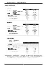
Page 28: ... 35 0 23 Burner Aeration Setting Fully open Fully open Supply Pressure 20 mbar 37 mbar Burner Operating Pressure 9 5 mbar 26 mbar Gas Regulator Cap Screw Natural Gas LP Gas Propane Open Burner Main Burner Ø 2 45mm Ø 1 50mm Pilot Burner PF Models Only 0 30 0 20 Griddle Main Burner Ø 2 10mm Ø 1 30mm Pilot Burner 0 35 0 23 Burner Aeration Setting Fully open Fully open Supply Pressure 1 13 3 40 kPa 2 ...

Page 29: ...r Ø 2 45mm Ø 4 50mm Pilot Burner PF Models only 0 30 0 60 Griddle Main Burner Ø 2 10mm Ø 3 40mm Pilot Burner 0 35 0 60 Burner Aeration Setting Fully open Fully open Supply Pressure 1 13 3 4 kPa 0 75 1 5 kPa Burner Operating Pressure 0 95 kPa 0 63 kPa Gas Regulator Cap Screw Adjustable Regulator Adjust to the Burner Operating Pressure specified LP Gas Propane Butane Open Burner Main Burner Ø 1 50mm...

Page 30: ...rol PF Models 227967 Knob Open Burner F Models 227384 Knob Open Burner PF Models 228167 Thermocouple Front 320mm Front 228166 Thermocouple Rear 600mm Rear Griddle 014105 Burner 032210 Injector Nat Gas Ø 2 10mm 032130 Injector LP Gas Ø 1 30mm 032120 Injector Butane Ø 1 20mm 032340 Injector Town Gas Ø 3 40mm 227403 Gas Control 227384 Knob Griddle 019215 Pilot Burner 026488 Pilot Injector Nat Gas 0 3...

Page 31: ...ase 900mm Plinth Kit 228805 Refrigeration Base 1200mm Plinth Kit For Refrigeration Cabinet Replacement Parts information refer to Refrigeration Cabinet Installation and Operation Manual supplied with appliance Gas Type Model Gas Regulators Part No Description Nat Gas LPG Butane RN8200G 228533 BSP F F Convertible 228531 BSP F F Convertible Town Gas ALL 230185 BSP F F Adjustable RN8400G RN8600G RN88...

Reviews: