OPERATOR’S MANUAL
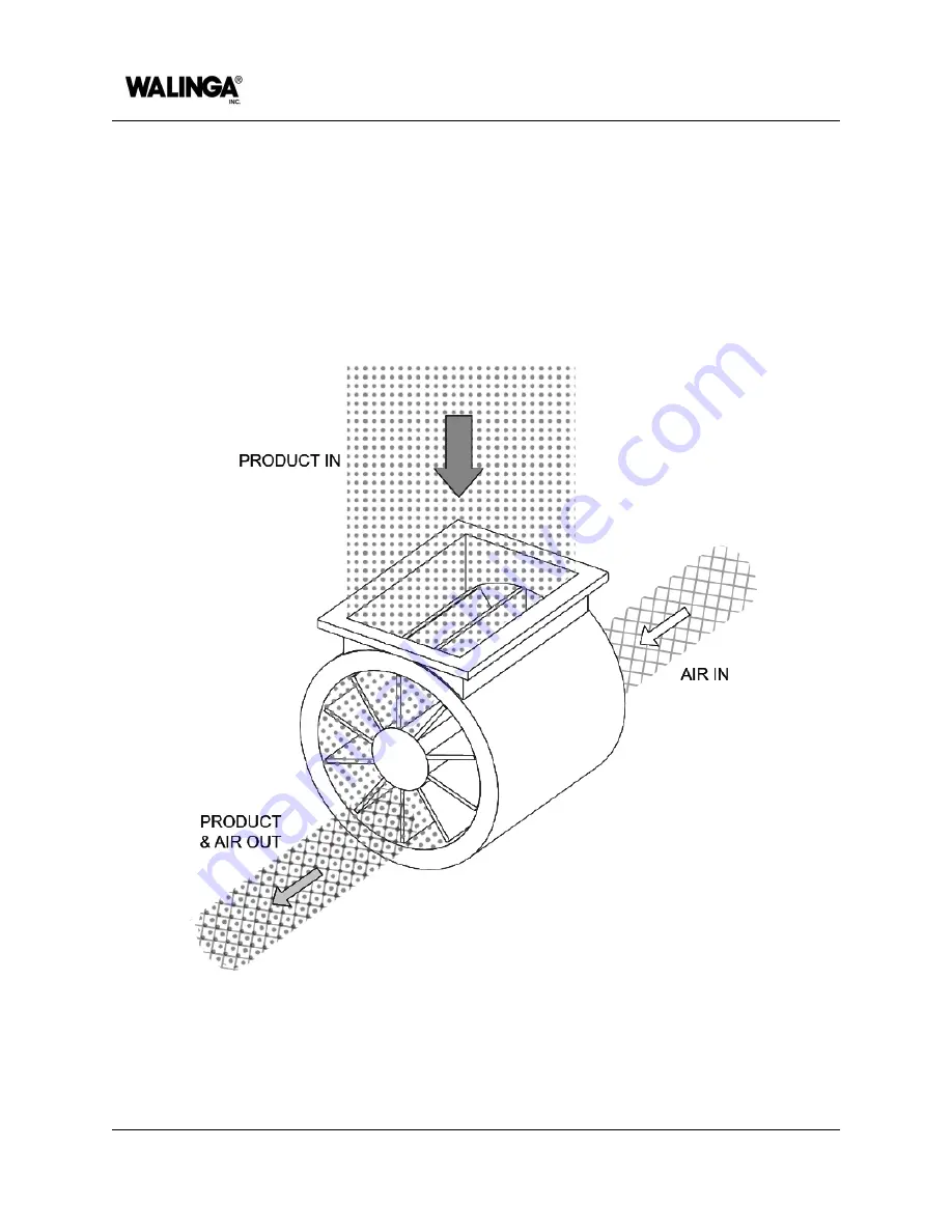
In the blow-thru model, as seen in
Figure 2-2
, a pressurized stream of air enters at the bottom
of the rear end plate. As the filled pockets rotate to the bottom, the product enters the
pressurized air stream and is carried through the outlet at the bottom of the front end plate to
the discharge side of the system. The motion of the discharged product is perpendicular to the
rotation of the airlock rotor. Blow-thru models will always function with a pressurized air stream
on the outlet side of the airlock, but can function with either vacuum or atmospheric pressure on
the inlet side.
Figure 2-2: Blow-thru style airlock
2-4
00-144472-0 A
INTRODUCTION
Summary of Contents for Airlock 1008
Page 1: ...OPERATOR S MANUAL Airlock 1008 English 00 144471 0 A 2023 12 06...
Page 7: ...Identification of Machine AIRLOCK MODELS 1 1...
Page 9: ...Introduction AIRLOCK MODELS 2 1...
Page 15: ...Machine Configuration AIRLOCK MODELS 3 1...
Page 26: ...OPERATOR S MANUAL PAGE INTENTIONALLY LEFT BLANK 3 12 00 144473 0 A MACHINE CONFIGURATION...
Page 27: ...Safety AIRLOCK MODELS 4 1...
Page 39: ...Machine Life Cycle Procedures AIRLOCK MODELS 5 1...
Page 45: ...Operation AIRLOCK MODELS 6 1...
Page 54: ...OPERATOR S MANUAL PAGE INTENTIONALLY LEFT BLANK 6 10 00 144476 0 A OPERATION...
Page 55: ...Maintenance and Adjustments AIRLOCK MODELS 7 1...
Page 99: ...Specifications AIRLOCK MODELS 8 1...
Page 108: ...OPERATOR S MANUAL PAGE INTENTIONALLY LEFT BLANK 8 10 00 144478 0 A SPECIFICATIONS...
Page 109: ...Warranty AFTERMARKET PARTS AND SERVICE 9 1...
Page 113: ...Accessories and Attachments AIRLOCK MODELS 10 1...
Page 116: ...OPERATOR S MANUAL PAGE INTENTIONALLY LEFT BLANK 10 4 00 144480 0 A ACCESSORIES AND ATTACHMENTS...
Page 117: ...Parts List AIRLOCK 1008 MODEL 11 1...
Page 125: ...PAGE INTENTIONALLY LEFT BLANK...


