


OPERATOR’S MANUAL
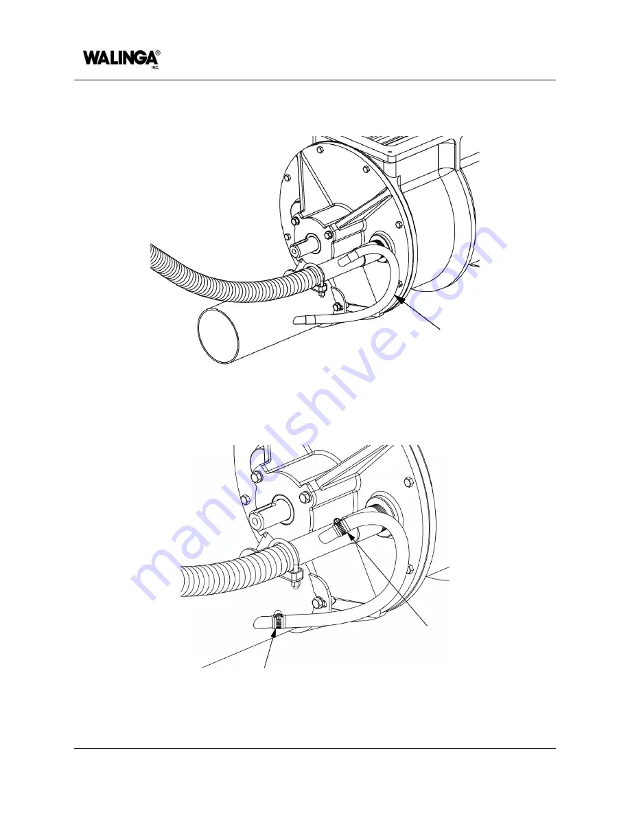
13. Use the rubber connector hose [
Item F
] to join the spigot of the air inlet assembly [
Item
E
] and vent pipe [
Item A
].
Figure 7-41: Connector hose installation
14. Secure the connector hose in place using hose clamps [
Item G
].
Figure 7-42: Gear clamp installation
15. Ensure all components and guards are properly installed and secured.
7-38
00-144477-0 A
MAINTENANCE AND ADJUSTMENTS
Summary of Contents for Airlock 1008
Page 1: ...OPERATOR S MANUAL Airlock 1008 English 00 144471 0 A 2023 12 06...
Page 7: ...Identification of Machine AIRLOCK MODELS 1 1...
Page 9: ...Introduction AIRLOCK MODELS 2 1...
Page 15: ...Machine Configuration AIRLOCK MODELS 3 1...
Page 26: ...OPERATOR S MANUAL PAGE INTENTIONALLY LEFT BLANK 3 12 00 144473 0 A MACHINE CONFIGURATION...
Page 27: ...Safety AIRLOCK MODELS 4 1...
Page 39: ...Machine Life Cycle Procedures AIRLOCK MODELS 5 1...
Page 45: ...Operation AIRLOCK MODELS 6 1...
Page 54: ...OPERATOR S MANUAL PAGE INTENTIONALLY LEFT BLANK 6 10 00 144476 0 A OPERATION...
Page 55: ...Maintenance and Adjustments AIRLOCK MODELS 7 1...
Page 99: ...Specifications AIRLOCK MODELS 8 1...
Page 108: ...OPERATOR S MANUAL PAGE INTENTIONALLY LEFT BLANK 8 10 00 144478 0 A SPECIFICATIONS...
Page 109: ...Warranty AFTERMARKET PARTS AND SERVICE 9 1...
Page 113: ...Accessories and Attachments AIRLOCK MODELS 10 1...
Page 116: ...OPERATOR S MANUAL PAGE INTENTIONALLY LEFT BLANK 10 4 00 144480 0 A ACCESSORIES AND ATTACHMENTS...
Page 117: ...Parts List AIRLOCK 1008 MODEL 11 1...
Page 125: ...PAGE INTENTIONALLY LEFT BLANK...


