800-WMAGNET
11 of 33
4.1.4 Workpiece Material
Low carbon steel such as SAE 1020 steel, are nearly as good conductors of magnetic lines of force as pure iron.
However, many other alloys contain non-magnetic materials which reduce the ability of magnetic lines of force to flow. An
alloy such as SAE 300 series stainless steel is almost as poor a conductor of magnetic lines of force as air.
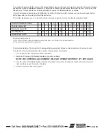
Type 416 stainless steel is considered magnetic, but it contains enough chromium so that a magnet can develop only
about one half as much magnetic force as it can on an SAE 1020 steel workpiece. Also, because of the carbon content,
the force developed on typical cast iron is less than one half that developed on SAE 1020 steel. (Chilled cast iron further
reduces the force to less than one quarter.)
Additional concerns regarding Magnetic Holding should be forwarded to O. S. Walker, Inc.
4.2 Full Holding
(Green Push-Button)
In the Full holding position, full output voltage is supplied from the control to the chuck as soon as this function is
selected. The indicator light for the Full holding position is illuminated when this function is selected.
NOTE: Full holding has equivalent holding force to 100% on the Variable holding control knob.
4.3 Variable Holding
(White Push-Button)
When the operator presses the Variable holding button, the output voltage of the control can be adjusted from zero to full with
the Variable control knob.
A varying amount of Residual hold can be achieved by turning the Variable control knob to zero from its previous holding
position without pressing the Residual button.
4.4 Residual Holding
The output of the control is reduced to zero when this function is selected. The control turns the chuck fully ON for a short
period of time, thus leaving a recognizable residual holding power in the chuck; this is called True Residual. During this brief
pulse, the indicator light, will be ON until another function is selected.
4.5 Release
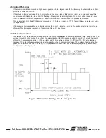
Selecting the Release function initiates an automatic release cycle. During the release cycle, the output voltage produced
by the control is reduced from full to zero in a predetermined number of equal pulses (see Figure 4 1). The polarity of these
pulses alternately reverses from negative to positive as the magnitude of the voltage decreases. The SMART-D can generate
a maximum of sixteen pulses per release cycle, but is set at the factory for eight.
The Release indicator light will flash ON and OFF to show that release is taking place, and will remain ON when the cycle is
complete.
The duration of each pulse is automatically controlled. The time between pulses is automatically adjusted by the control for
the optimum Release cycle time.
The SMART-D has an external and internal adjustment for the number of pulses per Release cycle. This adjustment allows
the operator to select the number of pulses it takes to get the fastest, most complete release of a part.
Summary of Contents for IMI Smart-D Series
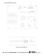
Page 18: ...800 WMAGNET 18 of 33 5 6 Smart 75 100D Panel Layout Figure 5 1 Smart 75 100D Panel...
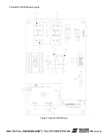
Page 19: ...800 WMAGNET 19 of 33 5 7 Smart 20 30 50D Panel Layout Figure 5 2 Smart 20 30 50D Panel...
Page 20: ...800 WMAGNET 20 of 33 5 8 Smart 7 10 15D Panel Layout Figure 5 3 Smart 7 10 15D Panel...
Page 21: ...800 WMAGNET 21 of 33 5 9 Smart 3 5D Panel Layout Figure 5 4 Smart 3 5D Panel...
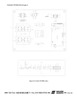
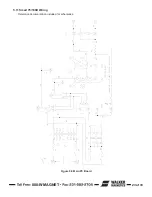
Page 22: ...800 WMAGNET 22 of 33 5 10 Main PC Board Figure 5 5 Main PC Board...
Page 30: ...800 WMAGNET 30 of 33 5 3 Remote Enclosure Dimensions Figure 5 12 Remote Enclosure BB 8783...
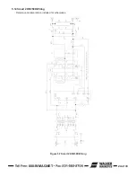
Page 31: ...800 WMAGNET 31 of 33 5 4 Remote Wiring Connections Figure 5 13 Remote Wiring Connections...
Page 34: ...1 800 W MAGNET WWW WALKERMAGNET COM 900632 A 07 21...


