800-WMAGNET
13 of 33
4.6 Control Protection
If the control is switched into sudden high power operation with too large a load, the AC fuse may blow before the electronic
protective circuits can function.
If the chuck control is overloaded by a short circuit or a chuck too large for this control’s rating, the control will sense this
condition and will attempt to protect itself by flashing all the system indicator lights, and the control will not respond to any
function selection. This will continue until AC power is removed from the control and the problem is corrected.
The logic section of the Main PC Board is protected by a .125A fuse in location F1. This fuse will blow if a problem occurs in
the logic section.
If AC power is interrupted while the control is running, the control returns to the mode of operation selected just prior to loss
of power. This allows easy resumption of machining after an AC line dropout.
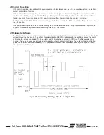
4.7 Release Cycle Steps
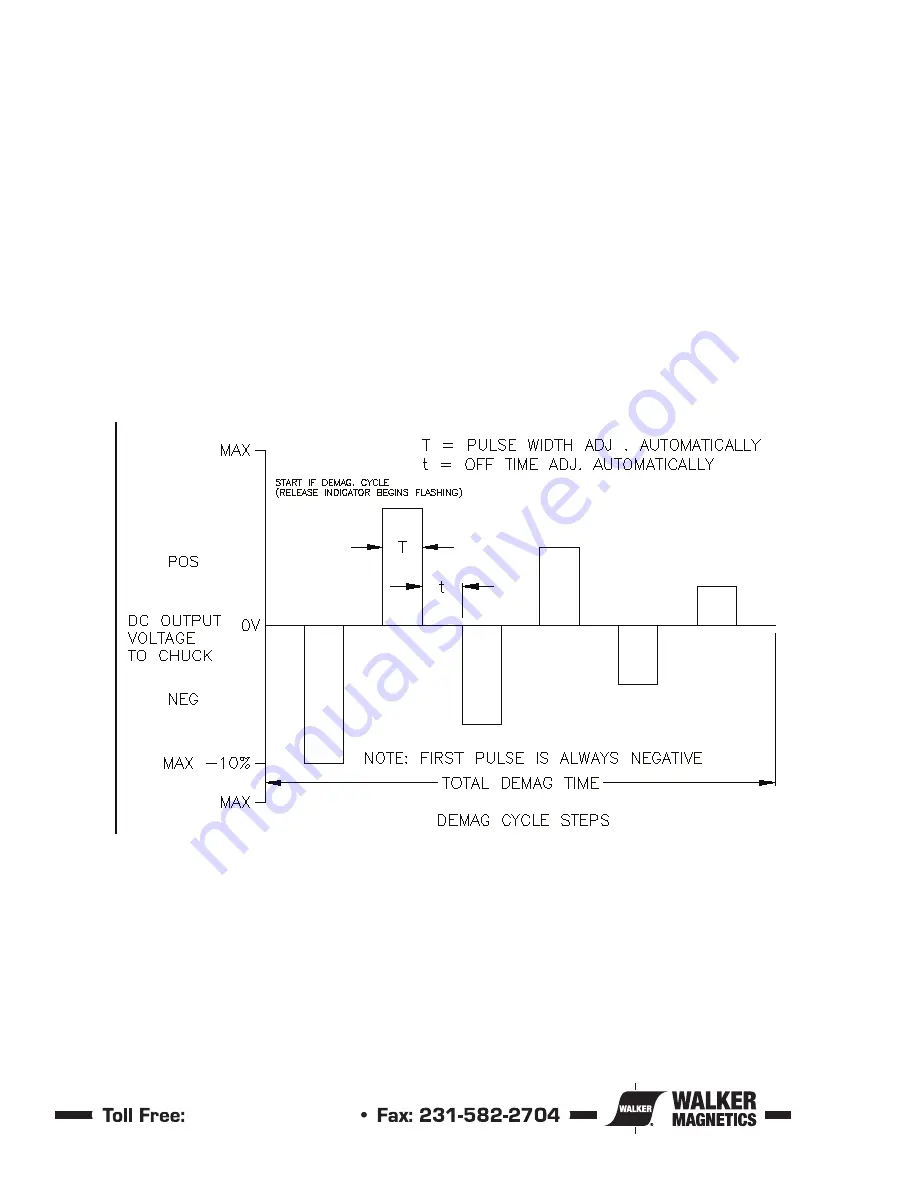
The Release Cycle removes residual magnetism in the chuck and workpiece by sending decreasing, alternating pulses of DC
voltage through the chuck coils. The amount of demagnetization (DEMAG) depends upon the number of pulses, the length
of time that the pulses are applied (T = Pulse width) and the time between pulses (t = Off Time). The first pulse is always
negative. The pulse voltages are determined automatically by the chuck control software. The number of demagnetization
pulses are adjustable from one to sixteen (1-16). The pulse width and off time are automatically adjusted by the on-board
microprocessor. See Figure 4 1.
Figure 4-1 Release Cycle Voltage VS. Release Cycle Time
Summary of Contents for IMI Smart-D Series
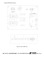
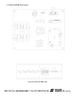
Page 18: ...800 WMAGNET 18 of 33 5 6 Smart 75 100D Panel Layout Figure 5 1 Smart 75 100D Panel...
Page 19: ...800 WMAGNET 19 of 33 5 7 Smart 20 30 50D Panel Layout Figure 5 2 Smart 20 30 50D Panel...
Page 20: ...800 WMAGNET 20 of 33 5 8 Smart 7 10 15D Panel Layout Figure 5 3 Smart 7 10 15D Panel...
Page 21: ...800 WMAGNET 21 of 33 5 9 Smart 3 5D Panel Layout Figure 5 4 Smart 3 5D Panel...
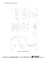
Page 22: ...800 WMAGNET 22 of 33 5 10 Main PC Board Figure 5 5 Main PC Board...
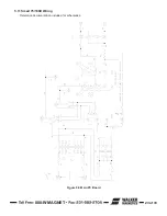
Page 30: ...800 WMAGNET 30 of 33 5 3 Remote Enclosure Dimensions Figure 5 12 Remote Enclosure BB 8783...
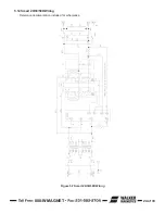
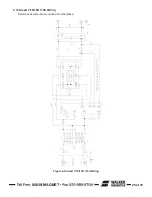
Page 31: ...800 WMAGNET 31 of 33 5 4 Remote Wiring Connections Figure 5 13 Remote Wiring Connections...
Page 34: ...1 800 W MAGNET WWW WALKERMAGNET COM 900632 A 07 21...


