800-WMAGNET
14 of 33
4.8 Grounding & Shielding
The optional chuck control outputs for current sense and part released are isolated from the control circuit ground. All other
chuck control electrical inputs and outputs, if connected to electronic equipment, must be isolated from the control’s internal
circuit ground, which is connected to the AC safety ground (the green or green/yellow wire in the AC line cord). The base of
the chuck is to be grounded to this point, as well as, through the ground wire of the DC chuck cable. All electrical chassis
must be safety grounded.
The chuck control’s DC power output leads
MUST BE SEPARATELY ROUTED
from other 115V level power leads in the
machine. They must not be routed in the same wire bundle with 400V or other high voltage leads. If the control has LOW
VOLTAGE signal leads wire through the machine, these
MUST BE SEPARATELY ROUTED
in their own SHIELDED
WIREWAY and the shield grounded to the machine chassis. Low voltage signals must not be routed with high voltage or high
power cables through any part of the machine, or electromagnetic interference may result.
4.8.1 Current Sensing
This control is equipped with a current sensing feature that monitors the current flowing to the chuck and indicates when this
current has reached a predetermined value. The predetermined value is set by adjusting the variable potentiometer to the
desired point and then pressing the residual pushbutton while holding down the variable pushbutton. When the preset value
is reached, the Variable indicator light stays on and the current sense relay closes. If the current flowing to the chuck goes
below the preset value, the variable light will flash. See section 3.1.8 for more information.
4.8.2 Part Release
When the control enters the Full and Variable modes Part Release relay energizes. When the control comes to the end of a
release cycle the Part Release relay de-energizes. See section 3.1.9 for more information.
4.8.3 Lockout
A Lockout feature is supplied with this control which prevents anyone from accidentally changing the settings while machining
is in progress. When the lockout signal is low (0V), the feature is disabled and when the signal is high (+5V), the feature is
enabled. The feature can be operated in two different manners. See section 3.1.10 for more information.
4.9 Control Output Voltage
The DC voltage for the magnet is connected across terminals 1 and 2 on TB1. This voltage may be measured
across these terminals and can vary from 0 115VDC and 0-230VDC depending on the model control and its
settings.
Summary of Contents for IMI Smart-D Series
Page 18: ...800 WMAGNET 18 of 33 5 6 Smart 75 100D Panel Layout Figure 5 1 Smart 75 100D Panel...
Page 19: ...800 WMAGNET 19 of 33 5 7 Smart 20 30 50D Panel Layout Figure 5 2 Smart 20 30 50D Panel...
Page 20: ...800 WMAGNET 20 of 33 5 8 Smart 7 10 15D Panel Layout Figure 5 3 Smart 7 10 15D Panel...
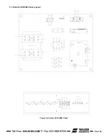
Page 21: ...800 WMAGNET 21 of 33 5 9 Smart 3 5D Panel Layout Figure 5 4 Smart 3 5D Panel...
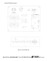
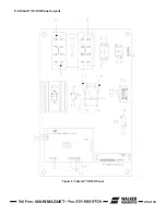
Page 22: ...800 WMAGNET 22 of 33 5 10 Main PC Board Figure 5 5 Main PC Board...
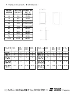
Page 30: ...800 WMAGNET 30 of 33 5 3 Remote Enclosure Dimensions Figure 5 12 Remote Enclosure BB 8783...
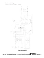
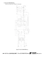
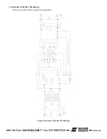
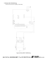
Page 31: ...800 WMAGNET 31 of 33 5 4 Remote Wiring Connections Figure 5 13 Remote Wiring Connections...
Page 34: ...1 800 W MAGNET WWW WALKERMAGNET COM 900632 A 07 21...


