800-WMAGNET
15 of 33
5 INSPECTION & MAINTENANCE
5.1 Daily Inspection
•
Check the physical condition of the power cords, indicating lamps, switches, and the control enclosure. If any
deficiencies are observed, contact your supervisor or O.S. Walker.
•
Check the integrity of the enclosure by inspecting for dust, debris, and fluid. Make necessary repairs.
•
Keep the outside of the enclosure free of dust and debris.
5.2 Having a Problem with your Chuck Control?
Problem
Probable Cause
Solution
1. All the remote unit
lights are flashing.
The load is drawing excessive
current and the control unit has
protected itself by disabling all
operating modes.
BEFORE PROCEEDING, DE-ENERGIZE THE
CONTROL UNIT.
a) Verify the chuck power rating does not exceed the control’s
power rating.
b) Disconnect the chuck from the control unit and verify that
the chuck’s coil windings are not shorted.
c) Repair/replace where required.
d) With the load disconnected, re-energize equipment
and cycle through all operating modes, verifying proper
operation.
e) Repeat step d. with the load reconnected.
f) Having successfully completed the above and unit does not
function properly, contact O.S. Walker, Inc.
2. None of the control
unit lights are
illuminated and it
does not respond
to any operating
mode
Input voltage is too low or wired
incorrectly. Remote unit is not
properly wired.
a) Verify the input voltage to the control unit (see Installation
section 3).
BEFORE PROCEEDING, DE-ENERGIZE THE
CONTROL UNIT.
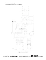
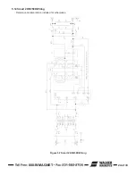
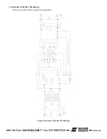
b) Verify that all fuses are good (see Standard Interface
Diagram section 5.3 for location). Use only exact
replacement fuses to avoid damaging unit or causing a
safety hazard.
c) Verify the wiring between the control unit and the remote
unit (see Standard Interface Diagram section 5.3).
d) Having successfully completed the above and the unit does
not function properly, contact O.S. Walker, Inc.
3. The fuse in the
control unit blows
when any of the
control modes are
selected.
Excessive current draw is
causing fuse to blow before
electronic protective circuits
have time to react.
BEFORE PROCEEDING, DE-ENERGIZE THE
CONTROL UNIT.
a) Visually inspect chuck cable and connections for pinches or
other damage.
b) Check chuck cable and connections for shorts with
ohmmeter.
c) Replace any questionable equipment.
d) Use only exact replacement fuses to avoid damaging the
unit or causing a safety hazard.
e) Re-energize equipment and cycle through all operating
modes, verifying proper operation, with the load
disconnected.
f) Repeat step e. with the load connected.
g) Having successfully completed the above and the unit does
not function properly, contact O.S. Walker, Inc.
Summary of Contents for IMI Smart-D Series
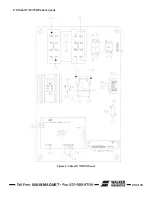
Page 18: ...800 WMAGNET 18 of 33 5 6 Smart 75 100D Panel Layout Figure 5 1 Smart 75 100D Panel...
Page 19: ...800 WMAGNET 19 of 33 5 7 Smart 20 30 50D Panel Layout Figure 5 2 Smart 20 30 50D Panel...
Page 20: ...800 WMAGNET 20 of 33 5 8 Smart 7 10 15D Panel Layout Figure 5 3 Smart 7 10 15D Panel...
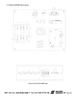
Page 21: ...800 WMAGNET 21 of 33 5 9 Smart 3 5D Panel Layout Figure 5 4 Smart 3 5D Panel...
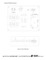
Page 22: ...800 WMAGNET 22 of 33 5 10 Main PC Board Figure 5 5 Main PC Board...
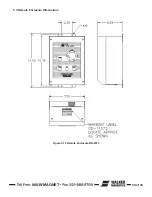
Page 30: ...800 WMAGNET 30 of 33 5 3 Remote Enclosure Dimensions Figure 5 12 Remote Enclosure BB 8783...
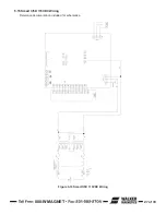
Page 31: ...800 WMAGNET 31 of 33 5 4 Remote Wiring Connections Figure 5 13 Remote Wiring Connections...
Page 34: ...1 800 W MAGNET WWW WALKERMAGNET COM 900632 A 07 21...


