800-WMAGNET
32 of 33
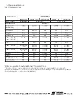
5.5 Replacement Parts List
Table 5-5 Replacement Parts
*Walker replacement parts may be installed by a **Designated Person.
** Designated Person - A person selected or assigned by the employer as being competent to replace specific
replacement parts listed in this manual and is able to verify the proper functioning of the specific replacement parts and
the entire product after the completion of the installation.
DESCRIPTION
PART NUMBER
SMART 3/5D
SMART 7-15D
SMART20-50D
SMART 75D
SMART100D
Main PC Board
39-DD14329
39-DD14520
39-DD14520A
Remote Control
56-BB8783
Transformer T1
(208/480 Volt)
12-0094
12-2001
12-0302
12-0504
12-0355
SCR Module
N/A
23-4048
N/A
N/A
N/A
Relay K1
N/A
13-0220
13-0344
N/A
N/A
Contactor K1
N/A
N/A
N/A
13-1300
13-0469
Fuse F1,F2 (500V)
Fuse F1,F2 (600V)
18-1011
18-1074
18-1234
18-1327
18-1336
Fuse 3
N/A
N/A
N/A
N/A
N/A
Fuse F1 (on pcb)
18-1340 CSA
18-1309
18-1340
18-1309
18-1340
18-1309
18-1340
18-1309
18-1340
18-1309
Fuse F2 (on pcb)
18-1341 CSA
18-1311
18-1341
18-1311
18-1341
18-1311
18-1341
18-1311
18-1341
18-1311
Diode D1
N/A
N/A
23-0212
N/A
N/A
SCR1,2
N/A
N/A
23-4051
N/A
N/A
Diode Module D1-D4
N/A
N/A
N/A
23-0221
23-0221
Solid State Relay
N/A
N/A
N/A
13-0459
23-0459
Summary of Contents for IMI Smart-D Series
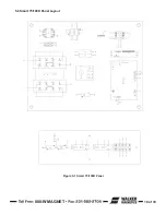
Page 18: ...800 WMAGNET 18 of 33 5 6 Smart 75 100D Panel Layout Figure 5 1 Smart 75 100D Panel...
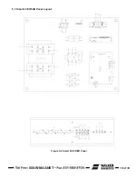
Page 19: ...800 WMAGNET 19 of 33 5 7 Smart 20 30 50D Panel Layout Figure 5 2 Smart 20 30 50D Panel...
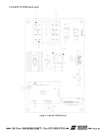
Page 20: ...800 WMAGNET 20 of 33 5 8 Smart 7 10 15D Panel Layout Figure 5 3 Smart 7 10 15D Panel...
Page 21: ...800 WMAGNET 21 of 33 5 9 Smart 3 5D Panel Layout Figure 5 4 Smart 3 5D Panel...
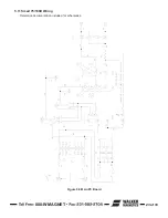
Page 22: ...800 WMAGNET 22 of 33 5 10 Main PC Board Figure 5 5 Main PC Board...
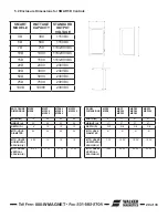
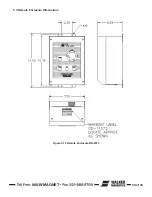
Page 30: ...800 WMAGNET 30 of 33 5 3 Remote Enclosure Dimensions Figure 5 12 Remote Enclosure BB 8783...
Page 31: ...800 WMAGNET 31 of 33 5 4 Remote Wiring Connections Figure 5 13 Remote Wiring Connections...
Page 34: ...1 800 W MAGNET WWW WALKERMAGNET COM 900632 A 07 21...

