800-WMAGNET
5 of 33
2.2 Recognize Safety Information
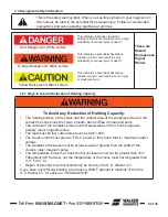
This is the safety alert symbol. When you see this symbol on your magnet or in
this manual, be alert to the potential for personal injury. Follow recommended
precautions and safe operating practices at all times.
Red Background, White Letters
This indicates a situation in which a
hazard is imminent and will result in a high
probability of serious injury or death.
These are
Hazard
Seriousness
Signal
Words
Orange Background, Black Letters
This indicates a potentially hazardous
situation, which could result in some
probability of serious injury or death.
Yellow Background, Black Letters
This indicates a potentially hazardous
situation, which could result in minor injury
or moderate injury.
2.2.1 Ways to Avoid a Reduction of Holding Capacity
To Avoid any Reduction of Holding Capacity:
•
The holding surface of the chuck and the contact area of the workpiece where it will
contact the chuck must be clean, smooth, flat, and free of nicks and burrs.
•
The surface of the workpiece must contact equal areas of the chuck’s opposite
polarity, major magnetic poles.
•
The load must be low carbon steel such as SAE 1020.
•
The chuck control must provide “FULL” power to the chuck, that is, maximum output
voltage.
•
The workpiece thickness must be at least equal or greater than the width of the
chuck’s major magnetic poles.
•
The temperature inside the chuck control enclosure must not be greater than 104°
Fahrenheit (40° Celsius), nor the temperature of the chuck must not be greater than
110° F (43° C).
•
Repair of this chuck control should only be done by the O. S. Walker Co.*
If you have any difficulty holding a work piece, DON’T attempt to machine it! Call the
O.S. Walker Co. for advice at 1-800-962-4638.
Summary of Contents for IMI Smart-D Series
Page 18: ...800 WMAGNET 18 of 33 5 6 Smart 75 100D Panel Layout Figure 5 1 Smart 75 100D Panel...
Page 19: ...800 WMAGNET 19 of 33 5 7 Smart 20 30 50D Panel Layout Figure 5 2 Smart 20 30 50D Panel...
Page 20: ...800 WMAGNET 20 of 33 5 8 Smart 7 10 15D Panel Layout Figure 5 3 Smart 7 10 15D Panel...
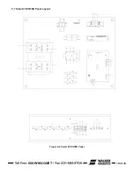
Page 21: ...800 WMAGNET 21 of 33 5 9 Smart 3 5D Panel Layout Figure 5 4 Smart 3 5D Panel...
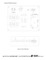
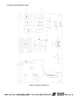
Page 22: ...800 WMAGNET 22 of 33 5 10 Main PC Board Figure 5 5 Main PC Board...
Page 30: ...800 WMAGNET 30 of 33 5 3 Remote Enclosure Dimensions Figure 5 12 Remote Enclosure BB 8783...
Page 31: ...800 WMAGNET 31 of 33 5 4 Remote Wiring Connections Figure 5 13 Remote Wiring Connections...
Page 34: ...1 800 W MAGNET WWW WALKERMAGNET COM 900632 A 07 21...


