
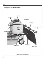


Assembly and Installation
A16
8
Assembly and Installation
ASSEMBLY
Follow these steps to assemble the spray tank prior
to installing it on the tractor. These steps must be
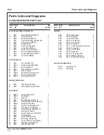
1. Install the left (P/N B029, #30) and right (P/N
B030, #38) Tank Supports on the bottom of the
tank. Install them with the single hole on the
side of the channel facing toward the front and
to the outside as shown in the parts diagram.
Use four (4) F091 5/16” x 5/8” hex bolts.
DO
NOT TIGHTEN ANY HARDWARE UNTIL
DIRECTED.
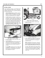
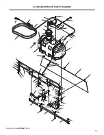
2. Install the Rear Support Brackets and Support
Tubes. The A16 ships with support brackets to
mount on most compatible decks. Differences
in the carrier frames require additional hard-
ware on a few of the decks (DS52, DS60, and
DS62). See the appropriate following section
for these decks.
NOTE:
The DC52R and the DM52A use a
different carrier frame than the DS52 and
therefore do not required additional mounting
hardware.
● If you are installing on a DS52 or DS60,
● If you are installing on a DS60, skip to the
section,
For All Compatible Decks (other than the
DS52, DS60, and DS62)
Use the two (2) included Rear Support Brack-
ets (P/N B028, #31).
a. Using two (2) F034 5/16” x 3/4” flange bolts
and F009 nuts mount each Rear Support
Bracket to the left and right Tank Supports
as shown in the parts diagram
.
b. Install the Support Tube (P/N B025, #35)
on the left and right Tank Supports in front
of the Rear Support Brackets using the two
U-bolts (B035, #34) and four (4) F427 5/16”
flange nuts into the appropriate set of
holes.
-
For the 42” and 48” carrier frames
, use
the
rear
set of holes closest to the Rear
Support Brackets.
-
For the 52” carrier frame
, use the
front
set of holes.
The tube should be installed with the holes
in the
vertical position
. The tube should
be positioned with
2-1/8” extending past
the Tank Supports on each end.
Tighten
all hardware installed.
c. Invert the unit, slide the left (P/N B027,
#33) and right (P/N B034, #37) Support
Tube Assemblies into the end of the Sup-
port Tube in a fully extended position.
d. Install the locking pins (P/N B026, #32) into
the tubes.
e. Continue the assembly with Step 3 install-
For DS52 and DS62
The following components must be purchased
separately to mount the sprayer on these
decks:
● Two (2) x B037 Mounting Bracket, 52/62
The included Rear Support Brackets (P/N
B028, #31) are not used with these decks.
a. Using two (2) F034 5/16” x 3/4” flange bolts
and F009 nuts mount each B037 Mounting
Bracket to the left and right Tank Supports.
(These brackets will be in the same posi-
tion as the #31 brackets in the parts draw-
ing.)
b. Install the Support Tube (P/N B025, #35)
using the holes immediately in front of the
Rear Support Brackets on the left and right
Tank Supports with (2) two U-bolts (B035,
#34) and four (4) F427 5/16” flange nuts.
The tube should be installed with the holes
in the
vertical position
. The tube should
be positioned with
2-1/8” extending past
the Tank Supports on each end.
Tighten
all hardware installed.


