


A16
Assembly and Installation
9
c. Invert the unit, slide the left (P/N B027,
#33) and right (P/N B034, #37) Support
Tube Assemblies into the end of the Sup-
port Tube. The RH assembly (P/N B034) is
fully extended on both the DS52 and DS62.
The LH assembly (P/N B027) is installed in
the center hole for the DS52 and is fully
extended for the DS62.
d. Install the locking pins (B026) into the
tubes.
e. Continue the assembly with Step 3 install-
For DS60
Order the following components to mount the
sprayer on this deck:
● Two (2) x B028-1 Support Bracket/60, Rear
The included Rear Support Brackets (P/N
B028, #31) are not used with this deck.
a. Using two (2) F034 5/16” x 3/4” flange bolts
and F009 nuts mount each B028-1 Support
Bracket to the left and right Tank Supports.
(These brackets will be in the same posi-
tion as the #31 brackets in the parts draw-
ing.)
b. Install the Support Tube (P/N B025, #35)
using the holes immediately in front of the
Support Brackets on the left and right Tank
Supports with two (2) U-bolts (B035, #34)
and four (4) F427 5/16” flange nuts.
The tube should be installed with the holes
in the
vertical position
. The tube should
be positioned with
2-1/8” extending past
the Tank Supports on each end.
Tighten
all hardware installed.
c. Invert the unit, slide the left (P/N B027,
#33) and right (P/N B034, #37) Support
Tube Assemblies into the end of the Sup-
port Tube in a fully extended position.
d. Install the locking pins (P/N B026, #32) into
the tubes.
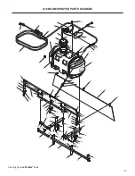
3. Install the Boom Supports (P/N B031, #36) on
the front of the left and right Tank Supports
using a F093
5/16-18 x 1 hex
bolt and a F020 nut.
4. Center the Main Boom (P/N B032, #39) on the
supports and place a Boom Extension (P/N
B033, #26) above the Main Boom on each end.
The end hole of each extension should line up
with the Main Boom’s second hole from each
end as shown in the parts diagram. Secure
each side with a F093 5/16-18 x 1 hex bolt and
F427 5/16-18 flange nut. Tighten these bolts
so the extensions can be moved by hand.
5. Install a F433 5/16-18 x 1/2 carriage bolt and a
F020 nut on each Boom Extension (P/N B033,
#26) in the second hole from the middle with
the head of the carriage bolt facing down so it
engages the large hole in the end of the Main
Boom when extended as shown in the parts
diagram.
6. Install the three (3) Wind Screen Supports (P/N
B036-2, #28) using a F646 3/8-16 x 3/4 serrat-
ed hex bolt, a F170 washer, and a F570 flange
top lock nut. Install the S-hooks (P/N B036-3)
for mounting the windscreen and squeeze
them to secure.
NOTE:
Keep the S-hooks loose enough that
the screen can be easily removed. The screen
should not be stored on the boom to protect it
from damage.
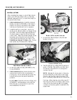
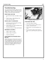
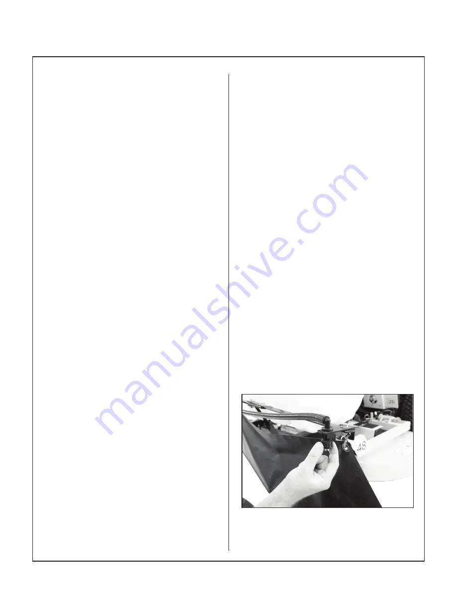
7. Install the hose assembly into the holes on the
Wind Screen Supports. The Tip Strainer (P/N
B015, #27) is inline with the Spray Tip (P/N
B014-1, #25), and the assembly is secured to
the Wind Screen Support with the Cap Nut
(P/N B016, #29) as shown in the parts dia-
gram. The spray tip must be positioned with the
slot parallel to the spray boom.
Install Hose Assembly


