
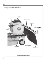


Assembly and Installation
A16
10
INSTALLATION
When installing the sprayer on your Walker tractor,
select a smooth, flat surface such as a driveway,
sidewalk, garage floor, etc. to mount the sprayer to
the deck’s carrier frame.
1.
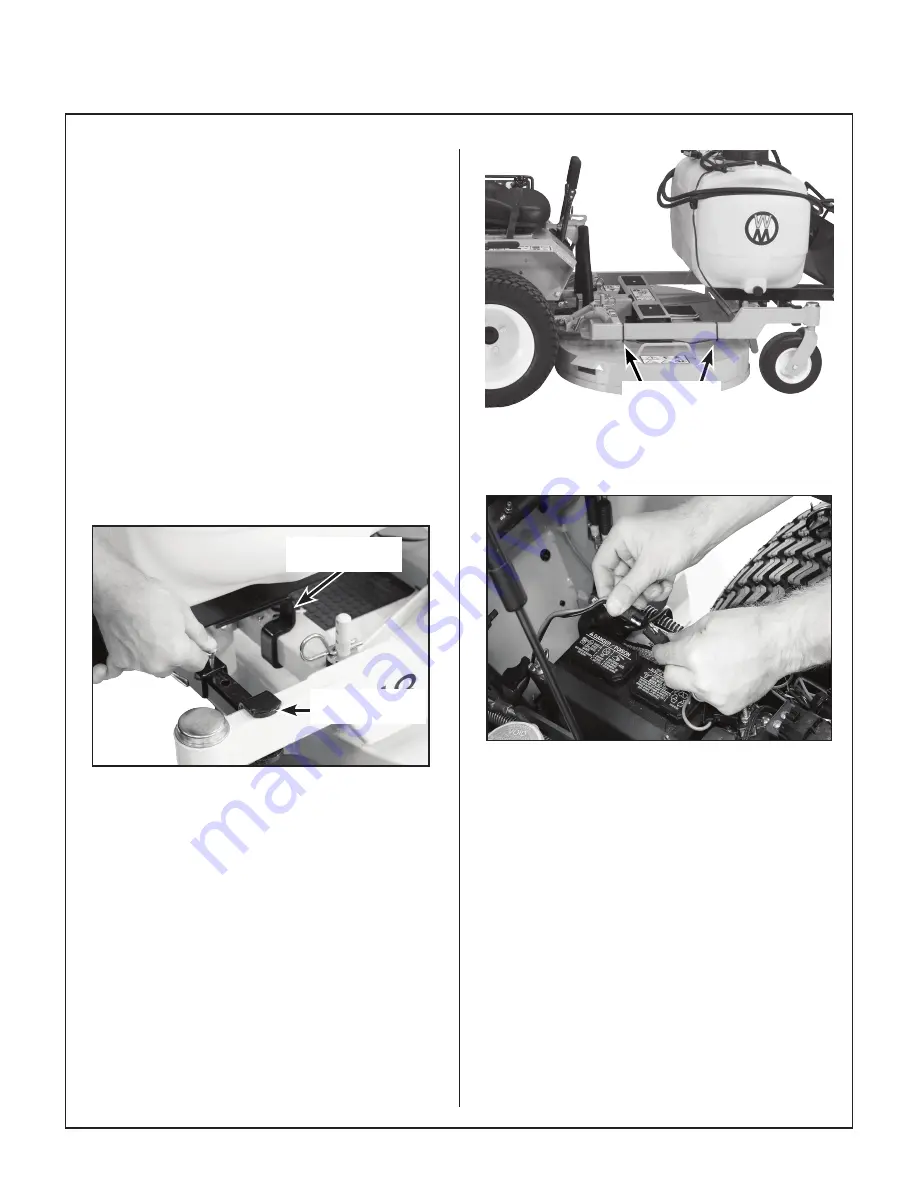
Initial Installation Only:
Install the Harness/
Battery Connector (P/N B005) to the tractor’s
battery. The red wire connects to the positive
terminal and the black wire to the negative.
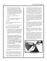
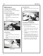
2. Install the sprayer on the deck. Leave one
locking pin in either the RH or LH Support Tube
Assembly. Hook the Rear Support Bracket of
the boom sprayer under the front of the deck
carrier frame. Slide the unlocked Support Tube
Assembly out to the deck carrier frame arm
and lock with the locking pin as shown in the
photo. If pin is
tight, gently tap into place with a hammer.
Rear Support
Bracket
Support Tube
Assembly
Install Boom Sprayer on Deck
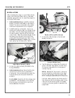
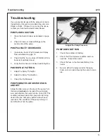
3. Connect the Wire Harness (P/N B004) to the
Pump (P/N B003).
4.
Initial Installation Only:
Route the Wire Har-
ness where it won’t be cut or pinched by a
moving part. It is recommended to secure the
harness with zip ties at several locations to
protect it.
For the DS60:
Install the 30” Wire Harness Ext
(P/N B005-1, sold separately) in line with the
Wire Harness as an extension to reach the
Harness/Battery Connector.
Zip Ties
Route and Secure Wire Harness
5. Connect the Wire Harness to the Harness/
Battery Connector.
Connect Wire Harness
6. Test the sprayer by putting about 5 gallons of
water in the tank. Operate the unit and check
the boom’s spray pattern for coverage and
overlap of spray.
NOTE:
Release the air pressure in the spray
wand to initiate the check valves in the spray
boom by opening the spray wand valve (P/N
B017) until spray material flows from the wand.
The base of the spray tips should be about 17”
from the ground for a good spray pattern. Also
check to see that the spray tips are installed
correctly so the spray pattern is parallel to the
spray boom.


