background image

A16 

Parts Lists and Diagrams

 15 

ITEM    PART 

DESCRIPTION 

    NO.       

 NO.    NO. 


REQ’D

ITEM    PART 

DESCRIPTION 

    NO.       

 NO.    NO. 


REQ’D

Use only genuine 

Walker

®

 parts.

Parts Lists and Diagrams

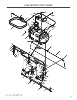
A16 BOOM SPRAYER PARTS LIST

Pump, Hose and Wand Components

B017 

Spray Wand W/Tip (#43238) 

1

B010 

Hose Clamp (3/8) 

5

B020 

Sump Strainer (#43258) 

1

B021 

Poly Straight Fitting (3/8) (#43182) 

1

B007 

Elbow, Poly 3/8 (#43183) 

1

B003 

Pump (#43178) 

1

B008 

Poly Tee (3/8) (#43235) 

1

B022 

In-Line Valve (#43014) 

1

B011 

Poly Tee Hose, 3/8 (43013) 

1

10 

B012 

End Tip Fitting W/Nut (#43011) 

2

11  

B013 

Tee Tip Fitting W/Nut (#43192) 

1

12 

B009 

Hose (3/8 x 20/Black) 

1

Tank Components

13 

B002 

Cap, Tank (#43175) 

1

14 

B002-1 

Rubber Gasket (#ST43882) 

1

15 

B019 

Hose Clip (#43191) 

1

16 

B018 

Spray Wand Holder (#43130) 

1

17 

B001-1 

Tank, 25 Gallon 

1

18 

5800-9 

Decal, Walker Round (4-3/4") 

2

19 

B022-1 

Decal, Caution (#43239) 

1

20 

B002-2 

Cap, Drain W/Washer 

1

Electrical Components

21 

B004 

Wire Harness (#43472) 

1

22 

B005 

Harness/Batt Conn(ST43483) 

1

Frame Mount

23 

B036-3 

S-Hook, Wind Screen 

3

24 

B036-1 

Wind Screen 

1

25 

B014-1 

Spray Tip 

3

26 

B033 

Boom Extensions (#43170) 

2

27 

B015 

Tip Strainer/Check Valve (#43016) 

3

28 

B036-2 

Support, Wind Screen 

3

29 

B016 

Cap Nut, Tip Fitting (#43012) 

3

30 

B029 

Tank Support, LH (#43320) 

1

31 

B028 

Support Bracket, Rear (#43319) 

2

32 

B026 

Locking Pins (#43317) 

2

33 

B027 

Support Tube Assy, LH (#43318) 

1

34 

B035 

U-Bolt (#43323) 

2

35 

B025 

Support Tube (#43316) 

1

36 

B031 

Boom Supports (#43168) 

2

37 

B034 

Support Tube Assy, RH (#43322) 

1

38 

B030 

Tank Support, RH (#43321) 

1

39 

B032 

Main Boom (#43169) 

1

Fasteners


F009 

5/16-18 Whiz Locknut 

4


F020 

5/16-18 ESNA Nut 

4


F025 

10-24 x 3/8 PPHMS 

2


F034 

5/16-18 x 3/4 Hex Bolt 

4


F091 

5/16-18 x 5/8 Hex Bolt 

4


F093 

5/16-18 x 1 Hex Bolt 

4


F170 

5/16 x 1 x 7/64 Flat Washer (Zinc Plate) 

3


F306 

3/8-16 x 3/4 Hex Bolt 

2


F396 

10-24 x 1-1/4 PPH Bolt 

4


F427 

5/16-18 Flange Nut 

6


F433 

5/16-18 x 1/2 Carriage Bolt 

2


F570 

3/8-16 Flange Top Lock Nut 

3


F646 

3/8-16 x 3/4 Serrated Hex Bolt 

3

Service Parts (Not Shown)


B017-1 

Spray Wand Tip


B003-1 

Pump Head

Summary of Contents for A16

Page 1: ...structions Compatible on decks 42 48 52 60 and 62 Please Read and Save These Instructions For Safety Read All Assembly and Operation Instructions Prior to Operating Attachment P N 7662 14 Release Date...

Page 2: ...understood to help prevent possible injury to the operator and others If anything in this manual is confusing or hard to understand please contact your local authorized dealer or call our service depa...

Page 3: ...0 Operating 11 Chemical Safety 11 Pump Operating Pressures 11 Calibrating the Application Rate 11 Operating the Sprayer 12 Installing the Wind Screen 12 Cleaning the Sprayer 12 Maintenance 13 Cleaning...

Page 4: ...tractor when the operator is seated facing forward in the tractor seat TRACTOR is the prime mover including the engine drivetrain operator seat and controls to operate the mower SPRAYER BOOM is the s...

Page 5: ...hown herein at any time without notice or obligation DECK COMPATIBILITY The A16 Boom Sprayer is supported on the following decks As new decks are added this list may not be complete so check with your...

Page 6: ...A16 3 A16 Boom Sprayer with Windscreen Component Identification Spray Boom Nozzle Boom Support Windscreen Tank Support Spray Boom Hose Assembly Spray Wand Pump Switch Wire Harness...

Page 7: ...ust take full responsibility for safety The Walker Rider Lawnmower has been designed with many safety features to protect the operator from personal harm or injury However it is neces sary for the ope...

Page 8: ...g the engine 12 Never attempt to make any adjustments while the engine is running except where specifically instructed to do so 13 The electrical system battery contains sulfuric acid Avoid any contac...

Page 9: ...aximum recommended slope operat ing angle is 15 degrees or 27 grade When operating the machine on a slope reduce speed and use caution to start stop and ma neuver To prevent tipping or loss of control...

Page 10: ...OID the warran ty and may cause hazardous conditions 7 Never attempt to disconnect any safety devices or defeat the purpose of these safety devices 8 Use genuine factory replacement parts Substitute p...

Page 11: ...P N B025 35 on the left and right Tank Supports in front of the Rear Support Brackets using the two U bolts B035 34 and four 4 F427 5 16 flange nuts into the appropriate set of holes For the 42 and 48...

Page 12: ...tion d Install the locking pins P N B026 32 into the tubes 3 Install the Boom Supports P N B031 36 on the front of the left and right Tank Supports using a F093 5 16 18 x 1 hex bolt and a F020 nut 4 C...

Page 13: ...r on Deck 3 Connect the Wire Harness P N B004 to the Pump P N B003 4 Initial Installation Only Route the Wire Har ness where it won t be cut or pinched by a moving part It is recommended to secure the...

Page 14: ...on and off at 100 PSI The spray wand has a flow rate of 1 gallon 3 78 L per minute At this flow rate the pump operating pressure will be about 60 65 PSI This operating pressure gives optimal continuo...

Page 15: ...wand valve P N B017 until spray material flows from the wand NOTE Never let the sprayer operate in one spot always turn the pump off when the tractor is stopped 6 Use the toggle switch to turn on the...

Page 16: ...er Spray Wand Tip 1 Unscrewed the Spray Wand Tip from the spray wand 2 Wash the tip under a faucet and reinstall Spray Wand Tip STORAGE OF THE SPRAYER Follow this procedure before storing the sprayer...

Page 17: ...tricting flow POOR SPRAY PATTERN 1 Adjust the Spray Tip height 2 Adjust the Spray Tip direction 3 Check the Tip Strainers PUMP VIBRATES OR SWITCHES ON AND OFF Adjust the Allen screw in the top of the...

Page 18: ...B004 Wire Harness 43472 1 22 B005 Harness Batt Conn ST43483 1 Frame Mount 23 B036 3 S Hook Wind Screen 3 24 B036 1 Wind Screen 1 25 B014 1 Spray Tip 3 26 B033 Boom Extensions 43170 2 27 B015 Tip Stra...

Page 19: ...36 32 37 31 38 28 29 30 31 35 34 34 33 32 26 27 25 28 29 39 11 9 10 27 25 28 2 23 10 24 18 23 8 2 5 4 3 F396 F025 F025 F020 F646 F170 F433 F570 F093 F646 F093 F020 F646 F570 F433 F570 27 25 F091 F009...

Page 20: ..._____________ __________________________________________________________________________________________ __________________________________________________________________________________________ ____...

Page 21: ..._____________ __________________________________________________________________________________________ __________________________________________________________________________________________ ____...

Page 22: ..._____________ __________________________________________________________________________________________ __________________________________________________________________________________________ ____...

Page 23: ...work is performed Warranty service can be arranged by contacting the dealer where you purchased the machine or by contacting Walker Manufacturing Company 5925 East Harmony Road Ft Collins CO 80528 Pr...

Page 24: ...WALKERMFG CO 5925E HARMONYROAD FORTCOLLINS CO80528 970 221 5614 FORM NO 122220 PRINTED IN USA www walker com 2020 WALKER MFG CO...

Reviews: