A16
1
General Information
HIGHLIGHTED INFORMATION
Walker Manufacturing recommends that any ser-
vice requiring special training or tools be performed
by an authorized Walker Mower dealer. There are
several general practices to be aware of in the
area of safety. Most accidents associated with the
operation or maintenance of a Walker Mower are
caused by disregarding basic safety precautions or
specific warnings. Such accidents, in most cases,
can be prevented by being aware of the dangers
present.
Information of special importance has been high-
lighted in bold type in this manual. Refer to
for the meanings of
DANGER, WARNING, CAUTION, IMPORTANT
,
and
NOTE.
GLOSSARY
There are many terms that are either unique to this
equipment or that are used as acronyms. The
following terms and their definitions will help while
using this manual:
●
LEFT HAND (LH)
refers to the left-hand side
of the tractor when the operator is seated
facing forward in the tractor seat.
●
RIGHT HAND (RH)
refers to the right-hand
side of the tractor when the operator is seated
facing forward in the tractor seat.
●
TRACTOR
is the prime mover, including the
engine, drivetrain, operator seat, and controls
to operate the mower.
●
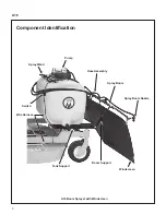
SPRAYER BOOM
is the spray nozzle support
consisting of a central main piece and two (2)
folding extensions mounted on the front of the
sprayer.
●
SPRAY WAND
is the handheld sprayer.
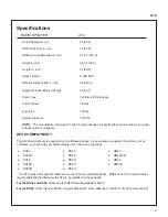
UNIT DESCRIPTION
The A16 Boom Sprayer utilizes a 25 gallon tank
and operates at 100 PSI. The unit has an actual
spraying time of about 42 minutes when using the
spray wand, or 20 minutes when using the boom
sprayer. The spray wand or the boom sprayer can
be selected using an electric switch located on the
on the unit, and accessible from the operator seat.
A windscreen is also included with the unit for use
in windy conditions.
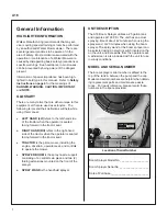
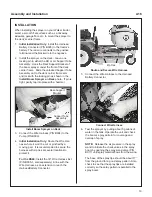
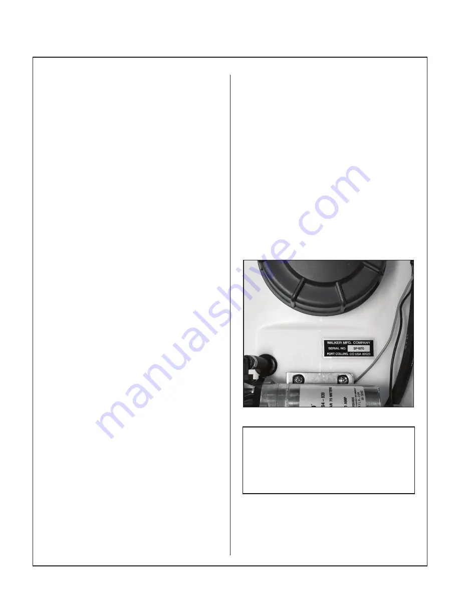
MODEL AND SERIAL NUMBER
The boom sprayer serial number is affixed to the
top of the tank in between the pump and the cap.
Model and serial numbers are helpful when obtain-
ing replacement parts and maintenance assis-
tance. For ready reference, please record these
numbers in the space provided.
Location of Serial Number
Boom Sprayer Model No. ___________________
Boom Sprayer Serial No. ___________________
Date of Purchase _________________________