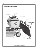
background image

Safety Instructions 

A16

 6

Release the steering levers and simultaneously 

(2) Move the FSC to the 

NEUTRAL-PARK


position.  When the machine is stopped or 

moving slowly, engage the parking brake.

NOTE:

  The emergency stop procedure is 

exactly the same procedure used to normally 

stop and park the machine.

6.  Disengage the PTO clutch and put the FSC in 

the 

NEUTRAL-PARK

 position before starting 

the engine (an ignition interlock switch normally 

prevents starting of the tractor if these controls 

are in the 

OPERATING

 position).

7. 

Do not operate machine if the operator 

presence safety switch system is not work-

ing.

  Verify proper operation by having the 

operator lift off the seat with the engine running 

and moving three controls, one at a time; (1) 

Move the FSC lever out of the 

NETRAL-PARK


position,  (2) Engage the PTO Clutch, and (3) 

Disengage the Parking Brake.  Moving any of 

these controls should stop the engine after a 

1/2 second delay.

8. 

Do not run the engine in a confined area 

without adequate ventilation.

  Exhaust fumes 

are hazardous and can be deadly. 

9. 

Do not carry passengers

 - maximum seating 

capacity is one (1) person. 

10. 

Avoid sudden starts or stops. 

 Before back-

ing the machine up, look to the rear to be sure 

no one is behind the machine.  Watch carefully 

for traffic when crossing or working near road-

ways. 

11.  When moving forward, 

do not

 suddenly put the 

tractor in reverse by rapidly pulling on the 

steering levers, especially when going down-

hill, as this can lift the tractor tail wheel off the 

ground and set up a bucking motion due to 

operator overcontrol.  If bucking does occur, 

immediately stop the bucking action by pulling 

the Forward Speed Control (FSC) lever into the 

NEUTRAL-PARK

 position.

12. 

The maximum recommended slope operat-

ing angle is 15 degrees or 27% grade.

 When 

operating the machine on a slope, reduce 

speed and use caution to start, stop, and ma-

neuver. To prevent tipping or loss of control of 

the machine, avoid sharp turns or sudden 

changes in direction.

 Do not operate the 

machine on a slope greater than 15 de-

grees.

13. 

Do not touch the engine or muffler while the 

engine is running

 or immediately after stop-

ping the engine.  These areas may be hot 

enough to cause serious burns. 

14.  When leaving the machine unattended, disen-

gage the PTO clutch, stop the engine, and 

remove the ignition key.

15. 

Do not use flammable materials


in the 

sprayer.

16.  Never allow the water hose used to fill the tank 

to reach down into the mixed spray solution.  

The end of the hose could be contaminated.

17.  Maintain a steady and slow speed when spray-

ing.  Be aware of changing weather conditions.  

Any blow back on the operator can be harmful.  

The chemicals can be absorbed via skin and 

inhalation.

18.  Spraying above shoulder height with the spray 

wand may cause the operator to be covered by 

blow back of mist leading to skin exposure plus 

mist inhalation.

19.  Always properly dispose of excess material in 

accordance with your local laws and the chem-

ical manufacturer’s guidelines.

20.  After each spraying session, always properly 

clean the sprayer for equipment longevity and 

to prevent accidents.

MAINTENANCE

NOTE:

  Refer to your tractor Operator’s Manual for 

safety instructions for tractor maintenance.

1. 

To prevent accidental starting of the engine 

when servicing or adjusting the machine, re-

move the key from the ignition switch and 

disconnect the fuel solenoid wire [diesel en-

gines] or the spark plug wire(s) [gasoline en-

gines].

2. 

To reduce fire hazards, 

keep the engine free 

of grass, leaves, excessive grease, and dirt.

3.  Keep all nuts, bolts, and screws tight 

to en-

sure the machine is in a safe, working con-

dition. 

Summary of Contents for A16

Page 1: ...structions Compatible on decks 42 48 52 60 and 62 Please Read and Save These Instructions For Safety Read All Assembly and Operation Instructions Prior to Operating Attachment P N 7662 14 Release Date...

Page 2: ...understood to help prevent possible injury to the operator and others If anything in this manual is confusing or hard to understand please contact your local authorized dealer or call our service depa...

Page 3: ...0 Operating 11 Chemical Safety 11 Pump Operating Pressures 11 Calibrating the Application Rate 11 Operating the Sprayer 12 Installing the Wind Screen 12 Cleaning the Sprayer 12 Maintenance 13 Cleaning...

Page 4: ...tractor when the operator is seated facing forward in the tractor seat TRACTOR is the prime mover including the engine drivetrain operator seat and controls to operate the mower SPRAYER BOOM is the s...

Page 5: ...hown herein at any time without notice or obligation DECK COMPATIBILITY The A16 Boom Sprayer is supported on the following decks As new decks are added this list may not be complete so check with your...

Page 6: ...A16 3 A16 Boom Sprayer with Windscreen Component Identification Spray Boom Nozzle Boom Support Windscreen Tank Support Spray Boom Hose Assembly Spray Wand Pump Switch Wire Harness...

Page 7: ...ust take full responsibility for safety The Walker Rider Lawnmower has been designed with many safety features to protect the operator from personal harm or injury However it is neces sary for the ope...

Page 8: ...g the engine 12 Never attempt to make any adjustments while the engine is running except where specifically instructed to do so 13 The electrical system battery contains sulfuric acid Avoid any contac...

Page 9: ...aximum recommended slope operat ing angle is 15 degrees or 27 grade When operating the machine on a slope reduce speed and use caution to start stop and ma neuver To prevent tipping or loss of control...

Page 10: ...OID the warran ty and may cause hazardous conditions 7 Never attempt to disconnect any safety devices or defeat the purpose of these safety devices 8 Use genuine factory replacement parts Substitute p...

Page 11: ...P N B025 35 on the left and right Tank Supports in front of the Rear Support Brackets using the two U bolts B035 34 and four 4 F427 5 16 flange nuts into the appropriate set of holes For the 42 and 48...

Page 12: ...tion d Install the locking pins P N B026 32 into the tubes 3 Install the Boom Supports P N B031 36 on the front of the left and right Tank Supports using a F093 5 16 18 x 1 hex bolt and a F020 nut 4 C...

Page 13: ...r on Deck 3 Connect the Wire Harness P N B004 to the Pump P N B003 4 Initial Installation Only Route the Wire Har ness where it won t be cut or pinched by a moving part It is recommended to secure the...

Page 14: ...on and off at 100 PSI The spray wand has a flow rate of 1 gallon 3 78 L per minute At this flow rate the pump operating pressure will be about 60 65 PSI This operating pressure gives optimal continuo...

Page 15: ...wand valve P N B017 until spray material flows from the wand NOTE Never let the sprayer operate in one spot always turn the pump off when the tractor is stopped 6 Use the toggle switch to turn on the...

Page 16: ...er Spray Wand Tip 1 Unscrewed the Spray Wand Tip from the spray wand 2 Wash the tip under a faucet and reinstall Spray Wand Tip STORAGE OF THE SPRAYER Follow this procedure before storing the sprayer...

Page 17: ...tricting flow POOR SPRAY PATTERN 1 Adjust the Spray Tip height 2 Adjust the Spray Tip direction 3 Check the Tip Strainers PUMP VIBRATES OR SWITCHES ON AND OFF Adjust the Allen screw in the top of the...

Page 18: ...B004 Wire Harness 43472 1 22 B005 Harness Batt Conn ST43483 1 Frame Mount 23 B036 3 S Hook Wind Screen 3 24 B036 1 Wind Screen 1 25 B014 1 Spray Tip 3 26 B033 Boom Extensions 43170 2 27 B015 Tip Stra...

Page 19: ...36 32 37 31 38 28 29 30 31 35 34 34 33 32 26 27 25 28 29 39 11 9 10 27 25 28 2 23 10 24 18 23 8 2 5 4 3 F396 F025 F025 F020 F646 F170 F433 F570 F093 F646 F093 F020 F646 F570 F433 F570 27 25 F091 F009...

Page 20: ..._____________ __________________________________________________________________________________________ __________________________________________________________________________________________ ____...

Page 21: ..._____________ __________________________________________________________________________________________ __________________________________________________________________________________________ ____...

Page 22: ..._____________ __________________________________________________________________________________________ __________________________________________________________________________________________ ____...

Page 23: ...work is performed Warranty service can be arranged by contacting the dealer where you purchased the machine or by contacting Walker Manufacturing Company 5925 East Harmony Road Ft Collins CO 80528 Pr...

Page 24: ...WALKERMFG CO 5925E HARMONYROAD FORTCOLLINS CO80528 970 221 5614 FORM NO 122220 PRINTED IN USA www walker com 2020 WALKER MFG CO...

Reviews: