background image

Safety Instructions - Before Operating

9

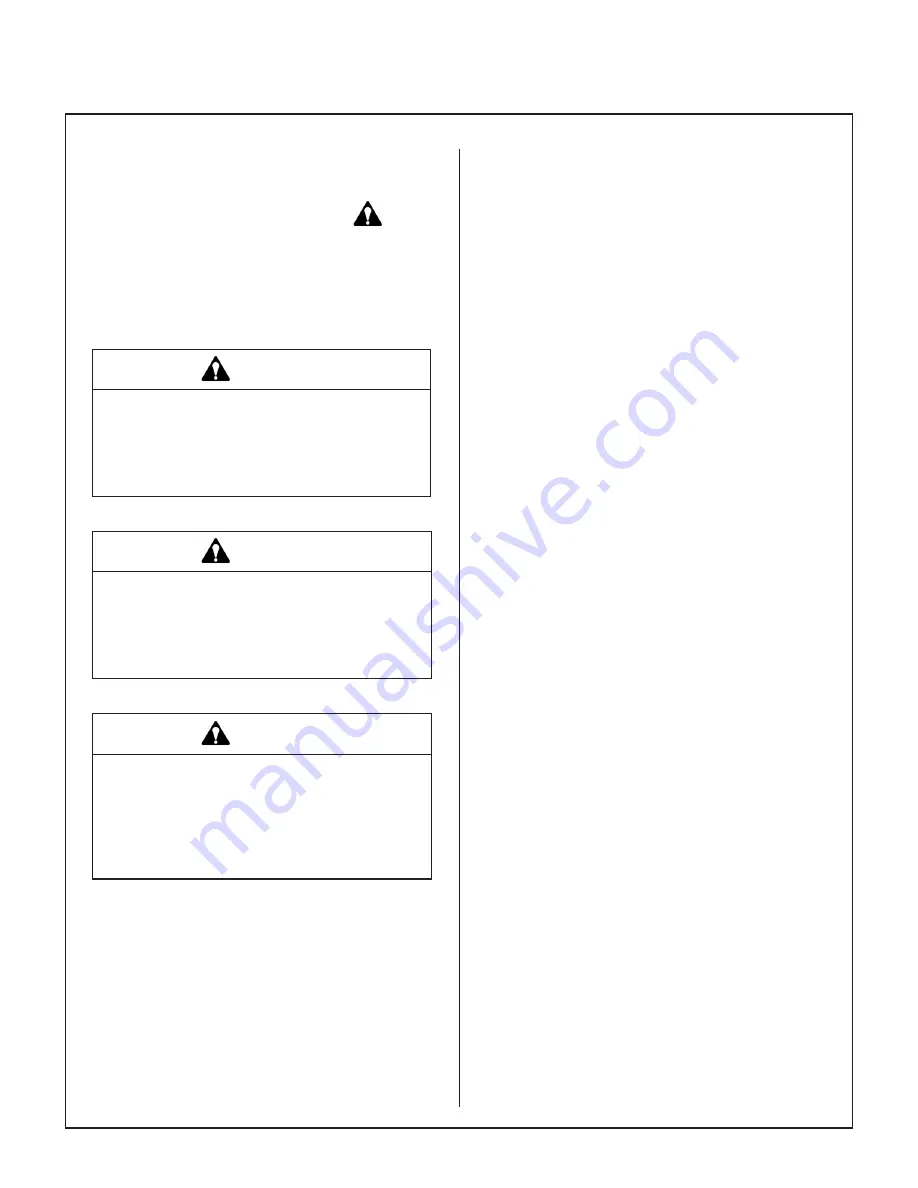
Pay particular attention to any information labeled 

DANGER, WARNING, CAUTION, IMPORTANT,


and 

NOTE

 in this manual.

When you see the Safety Alert Symbol ( 

 ), read, 

understand, and follow the instructions.  Fail ure to 

comply with safety instructions may result in person­

al injury.

The seriousness or degree of importance of each 

type of information is defined as follows:

  DANGER

An IMMEDIATE hazard that WILL result in 

severe personal injury or DEATH, if warn- 

ing is ignored and proper safety precau - 

tions are not taken.

  WARNING

A POTENTIAL hazard that COULD result in 

severe personal injury or DEATH, if warn-

ing is ignored and proper safety precau-

tions are not taken.

   CAUTION

Possible hazards or unsafe practices that 

MAY result in MODERATE personal injury 

or property damage, or machine damage, if 

warning is ignored and proper safety pre-

cautions are not taken.

IMPORTANT: 

Identifies mechanical information 

demanding special attention, since it deals with the 

possibility of damaging a part or parts of the ma­

chine.

NOTE: 

Identifies  information  worthy  of  special  

attention.

Walker Manufacturing cannot predict every poten­

tially dangerous situation.  Therefore, items labeled 

as such in this manual do not cover all conceivable 

situations.  Any person using procedures, tools, or 

control techniques not recommended by Walker 

Manufacturing must take full responsibility for safety.

The Walker Rider Lawnmower has been designed 

with many safety features to protect the operator 

from personal harm or injury.  However, it is neces­

sary for the operator to use safe operating proce­

dures at all times.  

Failure to follow safety instruc-

tions contained in this manual may result in 

personal injury or damage to equipment or prop-

erty.

If you have any questions concerning setup, opera­

tion, maintenance, or safety, please contact your 

authorized Walker Mower dealer or call Walker  

Manufacturing Company at (970) 221­5614.

BEFORE OPERATING

1. 

Read and understand the contents of this 

Operator’s Manual before starting and oper-

ating the machine.  

Become thoroughly famil­

iar with all machine controls and how to stop the 

machine and disengage the controls quickly.  

Replacement Operator’s Manuals are available 

by sending the Model and Serial Number to:

Walker Manufacturing Company

5925 East Harmony Road

Fort Collins, CO 80528

2. 

Never allow children to operate rider mower.  

Do not allow adults to operate without proper 

instruction.

3. 

Clear the area to be mowed of any foreign 

objects

 which may be picked up and thrown by 

cutter blades.  Pick up all sticks, stones, wire, 

and any other debris.

4.   Keep everyone, especially children and pets, a 

safe distance away from the area being mowed.  

Do not mow with bystanders in the area.

5.   Do not operate the machine barefoot or wearing 

sandals, sneakers, tennis shoes, or similar 

light weight footwear.  

Wear substantial pro-

tective footwear.

Summary of Contents for H38i

Page 1: ...anual Safety Assembly Operating and Maintenance Instructions Please Read and Save These Instructions For Safety Read All Safety and Operation Instructions Prior to Operating Machine Beginning S N 147211 P N 2000 21 ...

Page 2: ...tor or others If any thing in this manual is confusing or hard to understand please contact your local authorized dealer or call our service department at 970 221 5614 for clarification before operating or servicing this mower This manual covers Model H38i with the Kohler Command Pro ECH980 38 HP Electronic Fuel Injection EFI gasoline engine All shields and guards must be in place for the proper a...

Page 3: ...______ 25 Operating Instructions______________ 28 CONTROL IDENTIFICATION LOCATION AND FUNCTION ______________ 28 Ignition Switch________________________ 28 Engine Throttle________________________ 29 Body Latch___________________________ 29 Forward Speed Control FSC ____________ 29 Steering Levers_______________________ 29 Blade Clutch PTO _____________________ 29 Parking Brake_____________________...

Page 4: ...____ 61 Safety Switch System__________________ 61 Forward Speed Control Friction Lock______ 61 Transmission Control Setting____________ 62 Neutral Park_________________________ 62 Straight Ground Tracking_______________ 62 REPLACING REPAIRING__________________ 63 Drive Belts____________________________ 63 Engine PTO Belt______________________ 64 Ground Drive Belt_____________________ 65 Deck Drive...

Page 5: ... to the left hand side of the tractor when the operator is seated facing forward in the tractor seat POWER TAKE OFF PTO transmits engine power to run the cutter blades REAR DISCHARGE RD discharges mowed material from the back of the mower deck RIGHT HAND RH refers to the right hand side of the tractor when the operator is seated facing forward in the tractor seat SIDE DISCHARGE SD discharges mowed...

Page 6: ...nts during the limited warranty period it is important to find a local authorized servicing agent of the com ponent manufacturer Any unauthorized work done on these components during the warranty period may void the warranty If you have any dif ficulty finding an authorized outlet or obtaining warranty service please contact our Service Depart ment for assistance Walker Manufacturing Company 5925 ...

Page 7: ...System Air Cooled Air Cleaner Engine Mounted Kohler Kohler P N 25 083 01 S Primary P N 25 083 04 S Safety Filter ELECTRICAL SYSTEM Battery 12 Volt 340 CCA Charging System Flywheel Alternator Charging Output 25 Amp DC Regulated System Polarity Negative Ground Ignition Electronic Capacitive Discharge Starter 12 Volt Electric Ring Gear Type Solenoid Operated Interlock Switches Ignition Lockout by Sea...

Page 8: ...d Brake Manual Belt Tightener Clutch and Band Brake Stops Blades within Five 5 Seconds of Disengagement TIRE SIZE Deck Caster Wheel 13 x 5 00 6 Pneumatic 4 Ply Drive 22 x 10 50 12 4 Ply Low Profile Tailwheel 13 x 5 00 6 Pneumatic 4 Ply TIRE PRESSURE PSI KPA Deck Caster Wheel 20 137 Drive 15 103 Tailwheel 20 137 DIMENSIONS Tractor and Mower Length in cm Tractor Only 69 175 Tractor Wheel Base 45 115...

Page 9: ...ven Side Discharge Belt Driven Rear Discharge Cutting Width in cm 52 132 60 152 64 163 Cutting Height in cm 1 to 5 2 5 to 13 Height Adjustment in cm 1 4 1 Increments 17 Positions Blade Length in cm 18 4 47 20 5 52 22 2 56 Number of Blades 3 Direction of Rotation Viewed from top of deck Clockwise Deck Suspension Torsion Flex Frame with Caster Wheels and Counterweight Springs Maximum Blade RPM 3840 ...

Page 10: ...s Deck Height Lift Chain Deck Tilt Up Bar Deck Support Arm Not Visible Counterweight Springs and Protective Covers Adjustable Footrest Adjustable Footrest Forward Speed Control FSC Friction Adjustment Deck Lift Foot Pedal Raises Deck Cutting Height Release Lever Cutting Height Adjustment Deck Support Arm Not Visible Tilt Up Latch Deck Tilt Up Socket Tilt Up Hook ...

Page 11: ...ew Adjustable Footrest Left Hand Drive Wheel Fuel Pickup Line Fuel Tank and Cap Cylinder Head Cooling Fins Not Visible Muffler Fuel Gauge Dipstick Not Visible Oil Fill Engine Air Cleaner Body Lift Handle Spread Axle Tail Wheel Tailpipe Muffler Heat Shield ...

Page 12: ...sion Reservoir Parking Brake Linkage LH Transaxle RH Transaxle PTO Clutch Lever Clutch Linkage Parking Brake Lever LH Transmission Control Rod EVAP Line Fuel Pickup Line Oil Fill Rubber Bumpers Body Support LH Transaxle Lockout Arm RH Transaxle Lockout Arm Dipstick Not Visible ECU Air Filter Cover Battery Fuel Gauge Roll Over Valve Oxygen Sensor Air Cleaner Oil Filter Fuel Filter Fuel Pump Low Pre...

Page 13: ...y Walker Manufacturing must take full responsibility for safety The Walker Rider Lawnmower has been designed with many safety features to protect the operator from personal harm or injury However it is neces sary for the operator to use safe operating proce dures at all times Failure to follow safety instruc tions contained in this manual may result in personal injury or damage to equipment or pro...

Page 14: ...e ENGAGED position NOTE There is a 1 2 second time delay func tion on the seat switch to avoid engine power interruption when driving over bumps 10 Handle gasoline with care Gasoline is highly flammable and its vapors are explosive a Use an approved fuel container b Never add fuel to a running engine or hot engine allow hot engine to cool several minutes c Keep matches cigarettes cigars pipes open...

Page 15: ...on interlock switch normally prevents starting of the machine if these con trols are in the OPERATING position 7 Do not operate machine if the operator pres ence safety switch system is not working Verify proper operation by having the operator lift off the seat with the engine running and mov ing two controls one at a time 1 Move the FSC lever out of the NEUTRAL PARK position and 2 Engage the PTO...

Page 16: ... deck in tilt up position 18 In case of a clogged or plugged mower deck a Disengage the blade clutch PTO engage the parking brake and turn the engine off before leaving the seat b LOOK to make sure blade drive shaft move ment has stopped before trying to un clog the system c Disconnect the spark plug wires d Never place hands under the deck use a stick or similar tool to remove clogged ma terial 1...

Page 17: ...s and fuel injectors contact your Walker dealer or authorized Kohler service dealer 8 Altering the equipment or engine in any manner which adversely affects its operation perfor mance durability or use will VOID the war ranty and may cause hazardous conditions 9 Never attempt to disconnect any safety devices or defeat the purpose of these safety devices 10 Do not change the engine governor setting...

Page 18: ...Warning carbon monoxide CO poisoning hazard CO emitted by a running engine can be deadly Do not operate indoors or in other enclosed areas Location Rear Body Near Muffler Part Number 8600 5 8600 5 1 1 Warning hot surface do not touch Location Deck Carrier Frame Part Number 8600 15 1 1 Warning lock deck tilt up hinge before operat ing the machine 1 Grease PTO shaft joints every 8 hours Location PTO...

Page 19: ...charge Shield DS60 Part Number 5848 3 1 Warning thrown object hazard Always keep the discharge shield in the low est position when operating Do not remove the discharge shield Location Top of Deck Housing Part Number 8653 1 1 1 Warning secure deck with straps and engage parking brake before transporting or trailering with deck tilted up Location Deck Height Adjuster Part Number 2748 1 5 0 127 4 5 ...

Page 20: ...zards Keep away from rotating shafts belts and other components Location Right Fender Part Number 2802 4 Location Underside of Rear Body Part Number 2107 5 1 Ground drive belt routing 2 PTO clutch belt routing 1 Warning do not operate the machine without a deck or other implement attached 2 Forward Speed Control Move lever forward to increase speed back to stop 3 Body Tilt Latch Raise lever to rel...

Page 21: ...otection when op erating the machine 4 Warning readOperator sManualbeforeservic ing or performing maintenance Engage parking brake Remove ignition key 5 Warning roll over hazard Do not operate on slopes greater than 15 degrees 6 Warning thrown object hazard Keep bystanders away from the machine when operating 7 Warning entanglement hazard Keep all guards in place while engine is run ning 8 Parking...

Page 22: ...ectronic Control Unit Always disconnect negative battery cable lead before charging battery and also unplug harness from ECU before per forming any welding on equipment Raise mower body up for battery access Check the battery for electrolyte level and charge The electro lyte level should be at the bottom of the vent wells 1 4 to 1 2 in 6 to 13 mm above plates If the specific gravity is less than 1...

Page 23: ...water or any other liquid during initial activation 2 Remove the filler caps and carefully fill each cell until the electrolyte is just above the plates 3 After the battery is filled with electrolyte replace the filler caps and charge the battery Refer to Battery Charging Battery Charging DANGER BATTERIES PRODUCE EXPLOSIVE GASES Charge the battery in a well ventilated area so that gases produced w...

Page 24: ...battery cap vents are open Improper venting of the battery COULD cause a battery explosion Battery Clamp Secured by Wing Nut s Battery Cable Connection Battery Installation Mower Deck Assembly Deck Caster Wheels Installation 1 Remove the bolts and washers from each deck caster wheel 2 Install wheel on fork using bolts and washers 3 Tighten the bolts and washers Deck Caster Wheel Installation Deck ...

Page 25: ... Refer to Mower Deck Installation photo for location of deck support arm Deck Support Arms Rubber Debris Guard Mower Deck Installation 2 First engage the LH deck carrier frame tube socket on the LH tractor support arm and then the RH arm into the RH tube socket Slide the deck onto the support arms and install lynch pins to secure deck Two 2 lynch pins are in cluded in Owner s Packet of materials 3...

Page 26: ...Installation Tool from quick disconnect ring and make sure the ring has snapped securely on the spline shaft Coupler Installation Tool Removal Shown with Debris Guard Removed for Clarity IMPORTANT DO NOT operate tractor with Coupler Installation Tool installed IMPORTANT To prevent damage to the mow er make sure the PTO quick disconnect is se curely locked on the tractor with the locking balls full...

Page 27: ...upport frame are jig welded and the deck support linkage is factory adjusted Within normal tolerances very little if any adjust ment should be required to level the deck Tire size and pressure will affect the levelness of the deck Assure that all tires tractor and deck caster wheels are properly inflated prior to checking deck levelness or performing the deck leveling procedure Measuring Deck Leve...

Page 28: ...t and or right front support chain clevises to level the deck 4 Measure the front to rear level of the deck using a straight edge as shown in the Deck Leveling illustration The rear measurement should be 1 4 in 6 mm to 3 8 in 10 mm higher than the front measurement If necessary adjust the right side height adjustment rod by lengthening it to lower the back of the deck or shortening it to raise the...

Page 29: ...DO NOT use gasoline containing greater than 10 ethanol DO NOT use additives such as carburetor cleaners deicers or moisture removing agents DO NOT use gasoline blended with methyl alcohol CHECK ENGINE CRANKCASE OIL LEVEL Check the engine crankcase oil level before use and after each 8 hours of continuous operation Refer to LUBRICATION for Checking Engine Crankcase Oil Level in Maintenance Instruct...

Page 30: ...is hazardous The tilt up deck is secured in the raised position using the following procedure 1 Remove the tilt bar from the stowed position on the carrier frame 2 Use the tilt bar to release the two 2 deck lock ing arms as shown in the Unlock Deck Arms for Deck Tilt Up illustration 2802 5 1 5 1 2 Tilt Bar Unlock Deck Arms for Deck Tilt Up 3 Fit tilt bar into the socket on front of deck hous ing a...

Page 31: ... should be torqued to 60 lb ft 81 N m and the blade mounting bolts on belt driven decks should be torqued to 70 lb ft 95 N m If blade sharpening is required refer to CHECKING SERVICING for Sharpen Mower Blades in Maintenance Instruc tions ADJUST MOWER CUTTING HEIGHT IF REQUIRED Refer to ADJUSTING CUTTING HEIGHT in Oper ating Instructions PERFORM ANY ADDITIONAL PROCEDURES called for on the MAINTENA...

Page 32: ...S is the START position When start ing the engine turn the key clockwise to the S position Do not hold the key in the S position longer than 10 seconds If the engine does not start return the key to the O position for at least 60 seconds before making a re start attempt Prolonged cranking can damage the starter motor and shorten battery life Release the key when the engine starts and it will retur...

Page 33: ...the steering levers overrides the FSC setting and slows or stops for ward travel Releasing the steering levers allows the tractor to resume forward travel at the speed set by the FSC lever To stop and park the machine the FSC lever is moved backward to the NEUTRAL PARK position Steering Levers Each drive wheel is controlled by its own indepen dent steering lever for both steering function and FORW...

Page 34: ...positive mechanical lock similar to the PARK posi tion on an automotive automatic transmission If the tractor is moving when the brake is engaged it will result in sudden stoppage and possible inter nal damage to the transaxle NOTE If pressure on the parking brake e g parked on a hill makes it impossible to release the parking brake with the parking brake lever move the mower gently forward or bac...

Page 35: ...e engine performance When this light illuminates during operation contact an authorized Kohler Ser vice dealer to diagnose the fault IMPORTANT Continued operation of the engine with an illuminated engine service light will result in sub standard performance and MAY cause engine damage if not corrected as soon as possible Over Temperature Warning Light Horn The over temperature warning light and ho...

Page 36: ...gnition system In addition there is a 30 amp fuse on the engine to protect the charging circuit Refer to the Kohler en gine manual included with the Owner s Packet of materials for information regarding this fuse Hourmeter The hourmeter which is located on the right front of the body displays operating time accumulated while the ignition switch is in the ON RUN position The hourmeter provides main...

Page 37: ...d out If you fail to do so your health may be affected and the risk of ac cident increased CAUTION Before the tractor is used the safety switch must be checked for proper function The operation of the switch is checked by having the op erator lift off the seat with the tractor moving forward and or the blades engaged this action should cause the machine to stop If a malfunction is de tected the tr...

Page 38: ...the cover and loosen the hexa gon nut size 13 mm situated behind it Set the armrests in the desired position 5 steps and tighten the hexagon nut Replace the cap onto the nut Re fer to Figure 4 For Lumbar Support adjustment turning the knob upwards sets the curve in the upper part of the back upholstery Turning the knob downwards sets the curve in the lower part of the upholstery Refer to Figure 5 ...

Page 39: ...tion of the Steering Levers RIGHT WHEEL STEERING LEVER LEFT WHEEL STEERING LEVER Forward Position No Control Change Neutral Park Position Reverse Drive Wheel Motion Position Idle Position Fast Throttle Position Engaged Position Disengaged Position Disengaged Position Engaged Position FORWARD SPEED CONTROL LEVER FSC Full Forward Ground Speed Position Intermediate Ground Speed Position Neutral Park ...

Page 40: ...nnect safety switches they are for the operator s protection 2 Move the throttle 1 4 to 1 2 open toward FAST Turn the ignition switch to the START position to start the engine Release the key to ON RUN posi tion as soon as the engine starts IMPORTANT DO NOT crank the engine con tinuously for more than 10 seconds at a time If the engine does not start turn the key to the OFF position and allow a 60...

Page 41: ...ng the mower DO NOT disconnect the safety switches they are for the operator s protection 2 Steer by pulling the lever on the side of desired direction of turn e g pull the LH lever to turn left To minimize the possibility of overcontrol use only one hand on both steering levers Beginning Recommendations are Learn operation of the mower in an open area away from buildings fences and ob structions ...

Page 42: ...ng both steering le vers backward to the NEUTRAL position trac tor not moving and then moving the FSC lever to the NEUTRAL PARK position NOTE If the tractor creeps forward or back ward with the FSC lever in the NEUTRAL PARK posi tion the transmission control needs to be ad justed Refer to ADJUSTMENTS for Step 3 Neutral Function Adjustment in the Maintenance Instructions ENGAGING THE BLADE DRIVE 1 ...

Page 43: ...NING A brake stops the cutter blades from free wheeling within five 5 seconds after dis engaging the clutch If the brake system malfunctions and the blades do not stop within five 5 seconds the brake should be repaired or replaced before operating the mower Contact your Walker dealer 4 Turn the ignition switch OFF WARNING Remove the key from the ignition switch when leaving the mower unattended Th...

Page 44: ...foot rests To adjust rotate the footrests upward and slide to the desired position Rotate the footrest down and insert the edge of the footrest into the nearest notch to lock in position Adjustable Footrest ADJUSTING CUTTING HEIGHT WARNING Never adjust cutting height while the mower is moving Before adjusting cutting height or servicing move the Forward Speed Control FSC into the NEUTRAL PARK posi...

Page 45: ...d released 1 Raise the body 2 Pull up on each transaxle lockout arm and move back to engage the step that holds the arm in the UP unlocked position 3 The mower will freewheel with the arms in the LOCKOUT position The levers must be in the highest position to completely unlock the trans axles Transaxle Lockout Arm Transaxle Lockout Arm Freewheel Position 4 After moving the mower release the arms pl...

Page 46: ...ng in Assembly Instructions Use an alternating stripe mowing pattern for best appearance and vary the direction of the stripe each time the grass is mowed to avoid wear patterns in the grass Avoid damage to the grass by slipping and skid ding of the drive tires Use smooth control move ments of the steering levers since the transaxles are power boosted controls and jerking the levers can easily sli...

Page 47: ...up configuration should only be used when the tractor is parked The tractor body should never be tilted for ward with the deck in the tilt up position This can cause the deck to unhook from the tractor and fall with considerable force potentially causing deck or tractor damage and or bodily injury When transporting a tractor with the deck in the tilt up position on a truck or trailer the deck shou...

Page 48: ...ck x 61 Check Adjust Blade Clutch x 74 Clean Transaxle Housing x 57 Change Engine Oil Filter x 46 Check Regap Spark Plugs x 60 Replace Fuel Filter x 67 Change Transaxle Oil and FilterΔΔ x 48 Check Fuel Lines and Clamps x 60 Replace Air Filter Element x 53 Service Battery x 58 Service Solenoid Shift Starter x ΔΔΔ Check PTO U Joints for Wear Looseness x 60 Replace Fuel Lines and Clamps x 60 Replace ...

Page 49: ... performance of the cooling system by starting the engine holding a hand adjacent to the cylinder head and feeling the cooling airflow DANGER Make sure to keep hands clear of exhaust pipe muffler and moving parts when checking airflow Operate the engine at full speed when mowing This allows the engine to produce full horsepower and move more cooling air through the engine cool ing fins Air Cleaner...

Page 50: ...an the area around the dipstick to keep any dirt or debris out of the engine 3 Remove the dipstick wipe off with a clean rag then reinsert the dipstick into the tube and press all the way down 4 Remove the dipstick again and check the oil level on the dipstick The oil level should be within the Operating Range on the dipstick between the L mark and the F mark IMPORTANT DO NOT operate engine withou...

Page 51: ... the drain plug Make sure it is tight ened to 10 lb ft 14 N m 9 Fill the crankcase with new clean oil Use only crankcase lubricants recommended by the en gine manufacturer Refer to Specifications in this manual or the engine owner s manual Use the recommended oil viscosity for the expected ambient temperature Oil with the correct vis cosity will aid starting in cold weather and as sure proper lubr...

Page 52: ... clean the exterior of the transmis sion housing before servicing Remove expan sion tank cap to allow venting Using a 1 4 in hex wrench remove the plug on the lower in side of each transaxle allowing the oil to drain 2 Remove the oil filter guard remove and replace the oil filter using an oil filter wrench Tighten filter by turning filter 3 4 to 1 turn after gasket contacts the filter base surface...

Page 53: ...rate at normal noise levels and move smoothly in for ward and reverse Grease Fitting and Oil Point Lubrication Lubricate the grease fittings and oil points after ev ery 25 hours of operation Lubricate more often when operating in dusty or dirty conditions Use SAE general purpose lithium or molybdenum base grease for grease fittings and light machine oil SAE 10 to lubricate oil points Lubricate the...

Page 54: ... Pivot Grease 1 15 ClutchArm Pivot Grease 1 16 Transaxle Oil Reservoir Oil 1 17 Throttle Control Cable Ends Oil 2 18 Engine Dipstick Oil 1 19 Tail Wheel Caster Fork Pivot Grease 2 20 RearAxle Pivot Grease 1 21 Rear Wheel Bearing Grease 2 22 Engine Oil Filler Oil 1 23 PTO Belt Tightener Pivot Grease 1 24 ClutchActuator Push Rod Grease 1 25 Brake Band Pivot Pins Clevis Oil 2 26 Parking Brake Pivot G...

Page 55: ...51 Maintenance Instructions LUBRICATION Chassis and Deck Lubrication Points 10 9 8 7 11 12 7 17 28 9 26 13 19 21 22 17 20 19 16 15 18 14 13 2 1 1 2 3 4 5 6 6 5 4 3 30 29 24 23 25 27 27 ...

Page 56: ...r filter installation Intake design and internal baffling provide dust separation and automatic precleaning action Daily or frequent servicing of the air cleaner is not required IMPORTANT Use only Kohler air filter elements for replacement Kohler 25 083 01 S and 25 083 04 S Aftermarket filters may not seal properly or filter ef ficiently Canister Primary Filter Element Air Cleaner Components Shown...

Page 57: ...primary filter element Replace the filter if any cracks tears or other damage to the sealing surface are noted 6 Without removing visually inspect the condi tion of the safety filter for damage or holes The safety filter should only be removed for re placement YEARLY or when dirty or dam aged IMPORTANT Prior to removing the safety filter make sure the inside surface of the air cleaner canister is ...

Page 58: ...screen dirty or plugged cooling fins and or cooling shrouds removed will cause engine damage from overheating Rotating Engine Cooling Air Intake Screen Keep Engine Screen Clean Cylinder Head Cooling Fins It is essential for performance and longevity of the air cooled engine to keep the cylinder head cooling fins clean and free of obstruction After every 8 hours of operation check the performance o...

Page 59: ...horoughly to prevent overheating and extend engine life Make sure cool ing shroud is reinstalled properly This procedure will require removing the engine from the chassis Engine Cylinder Head Access Panels Kohler Engine Cooling Shroud Rotating Engine Cooling Air Intake Screen Rotating Engine Cooling Air Intake Screen and Cylinder Head Access Panels Oil Cooler Cooling Fins Oil Line Remove Access Pa...

Page 60: ...Bar Tilt Up Hook and Latch Connected Tilt Up Hook Tilt Up Latch Hitch Pin Deck Secured in TILT UP Position 6 Clean grass buildup underneath the deck using a pressure washer and scraper if required NOTE If the buildup is severe it may be easier to clean the deck by removing the deck assem bly from the tractor and standing the deck as sembly on its nose NOTE While some degree of material buildup in ...

Page 61: ...housing use compressed air and or a pressure washer Pay close attention to any oily dirt buildup on the transaxle housings This may be the result of an oil leak If an oil leak is noticed contact your local Walker dealer Cooling Fins Transaxle Housing and Cooling Fins IMPORTANT In case an oil leak develops on the input shaft the cooling fan blowing dusty air and oil on the transmission will quickly...

Page 62: ...N Important Battery Service Installation and Charging Tips for Electronic Fuel Injected Engines Do not allow the battery cables to touch opposing terminals When connecting battery cables attach the positive cable to positive battery terminal first fol lowed by negative cable to negative battery terminal Never start the engine when the cables are loose or poorly connected to the bat tery terminals ...

Page 63: ...ck Caster Wheel 20 PSI 137 kPa Drive 15 PSI 103 kPa Tailwheel 20 PSI 137 kPa Wheel Nut Torque Check the eight 8 Drive Tire mounting nuts Every 100 hours they should each be torqued to 75 to 85 lb ft 102 to 115 N m Sharpen Mower Blades Check mower blade s for straightness sharp ness condition of the cutting edge and balance every 10 hours of operation or more often when mowing abrasive type grass o...

Page 64: ...and bolt Tighten the bolt to 70 lb ft 95 N m Drive Belts Raise the body and inspect the condition of the four 4 drive belts after every 25 hours of operation engine PTO drive 3 and ground drive 1 Also re move the belt cover on the mower deck and check the blade drive belt If the belts show signs of cracking or deteriorating the belts should be re placed Refer to REPLACING REPAIR ING the Drive Belt...

Page 65: ...s occur during start ing or operating a safety interlock switch may be malfunctioning Contact your Walker dealer for trou bleshooting and or replacement With or without an operator in the seat the en gine starts with the Forward Speed Control FSC and or the PTO engaged With an operator in the seat the engine starts but dies soon after the Forward Speed Control FSC or PTO is engaged Without an oper...

Page 66: ...n there should be no movement of either drive tire If the tire s are creeping forward or re verse refer to ADJUSTMENTS for the Neutral Function Adjustment Step 3 in this section Straight Ground Tracking Check for straight ground track by driving on a smooth level surface with hands off the steering le vers Set the FSC at different speeds and observe if the mower moves in a straight line use a ceme...

Page 67: ...se genuine factory re placement parts Substitute parts CAN result in product malfunction and possible injury to the oper ator and or others Drive Belts There are five 5 individual drive belts on the ma chine Engine PTO Belt Matched Set of 3 Ground Drive Belt Mower Blade Drive The belts may be removed and replaced using the procedures described on the following pages Belt Locations Engine Hidden fo...

Page 68: ... Hidden for Clarity 2 To replace an engine PTO belt a Reverse the removal procedure to replace an engine PTO belt b Secure wire on lock pin above tab on lower PTO guard Engine PTO Belt Belt Guards Closed Engine Hidden for Clarity PTO Guard Secure Wire Above Tab Front View Right Hand Guard Secure Wing Nut Lower LH Guard Wire Lock Pin Upper LH Guard Secure Wing Nut PTO Guard Wire Lock Pin Wire Lock ...

Page 69: ...the idler pulley 2 Reverse the procedure to install the ground drive belt Ground Drive Belt Assembly Disengaged Ground Drive Belt Assembly Engaged Raise Idler Pulley to Relax Belt LH Transaxle Ground Drive Belt RH Transaxle Drive Pulley Transmission Belt Tensioner Arm Deck Tilt Bar Belt Tightener Idler Pulley LH Transaxle Ground Drive Belt RH Transaxle Drive Pulley Transmission Belt Tensioner Arm ...

Page 70: ... then slip off the LH spindle pulley and can be completely removed 2 Install the deck drive belt by reversing the re moval procedure a Route the belt as shown on the belt routing decal located on the deck housing Leave the belt loose at the LH spindle and then install the belt by compressing the belt ten sioner as noted above b After the belt is in place reset the belt ten sioner stop bolt by turn...

Page 71: ...ECKING SERVICING to Sharpen Mow er Blades in this section During the course of sharpening and inspecting mower blades if there are any of the following conditions of wear or dam age blades should be replaced for reasons of safe ty and performance of the machine An excessive amount of the flat section of the blade has been ground away removed when the blade is sharpened Replace the blade when less ...

Page 72: ...cedure from Sharp en Mower Blades instructions If blades are re placed always use Walker original equipment blades to ensure safety and optimum performance The quality and performance of replacement blades offered by other manufacturers cannot be guar anteed they could be dangerous CAUTION ALWAYS use genuine factory replace ment parts Substitute parts CAN result in prod uct malfunction and possibl...

Page 73: ... other If they are not equal adjust accordingly The handles may or may not be even at this point NOTE The LH steering lever is non adjust able This procedure will require adjustment of the RH lever to make it even with the LH lever Levers should sit parallel to each other Lever Alignment 2 Adjust the position of the RH lever by turning the stop bolt in the Speed Control Actuator in or out Turning ...

Page 74: ...justment 2 Securely block the tractor up so the drive tires are off the ground 3 Adjust the tracking adjustment nuts at the front of both control rods so that 2 or 3 threads are visible then loosen the jam nuts on the ball joints at the back of the control rods Control Arm Tracking Adjustment Nuts Control Rods Transmission Control Rod and Arm Location Front Body Hidden for Clarity FWD REV Tracking...

Page 75: ...d Speed Adjustment 1 Move the FSC to the full FORWARD speed po sition 2 Raise the body The set screws in the left and right Transmission Control Arms should not be contacting the locating stud in the transaxle If they are back the set screws out until they do not touch T Handle Hex Wrench Maximum Speed Tracking Adjustment Transmission Control Arm Maximum Speed Tracking Adjustment Shown with Parts ...

Page 76: ...e and engage the parking brake to pre vent accidental starting and inadvertent machine movement 2 Check operation of the FSC Neutral Switch by placing the FSC lever in the full FORWARD position While holding the ignition switch in the START position slowly move the FSC lever back towards the NEUTRAL PARK position until the starter motor engages Stop moving the lever and note the position of the FS...

Page 77: ...tion is increased or decreased by tightening or loosening the friction adjust ment nut Loosen or tighten the nut and check the control function until the conditions of both steps 1 and 2 above are met FSC Friction Adjustment Nut FSC Friction Adjustment Nut ...

Page 78: ... proceed with adjustment as follows Adjust the length of the clutch actuator link to achieve a clutch spring assembly bolt head clear ance of 1 4 in to 5 16 in 6 35 mm to 7 94 mm with the clutch engaged To adjust length remove ball joint from clutch arm and shorten the clutch actuator link to increase this measurement or lengthen the clutch actuator link to decrease this measurement If adjustments...

Page 79: ...ve 5 seconds after disengaging the clutch Use the following procedures to check and adjust clutch disengagement and brake action Step 1 Idler Pulley Maximum Travel Adjustment Loosen the brake band adjustment nut allowing clutch pivot stop arm and stop bolt to make contact refer to Blade Brake Band Adjustment illustra tion 1 To check the pulley travel first engage the clutch then measure the distan...

Page 80: ...essary to adjust the blade brake band nut to maintain these dimensions CLUTCH DISENGAGED CLUTCH ENGAGED 5 8 in to 3 4 in 16 mm to 19 mm Clutch Idler Pulley Travel Adjustment Blade Brake Band Blade Brake Band Adjustment Nut Chassis Mount Ref Blade Brake Band Adjustment 2 After adjustments are complete check blade brake action as described in CHECKING SER VICING the Blade Brake Action in this sectio...

Page 81: ..._________________________ ______________________________________________________________________________________________________________ ______________________________________________________________________________________________________________ ______________________________________________________________________________________________________________ _________________________________________...

Page 82: ..._________________________ ______________________________________________________________________________________________________________ ______________________________________________________________________________________________________________ ______________________________________________________________________________________________________________ _________________________________________...

Page 83: ... follow the instructions contained in the Operator s Manual for operation and maintenance B The customer shall pay any charges for making service calls and or for transporting the mower to and from the place where the inspection and or warranty work is performed 3 HOW TO OBTAIN SERVICE UNDER THIS WARRANTY Warranty service can be arranged by contacting the dealer where you purchased the mower or by...

Page 84: ...WALKERMFG CO 5925E HARMONYROAD FORTCOLLINS CO80528 970 221 5614 FORM NO 042518 PRINTED IN USA www walker com 2018 WALKER MFG CO ...

Reviews: