background image

Maintenance Instructions

KAWASAKI TIPS

41

IMPORTANT TIPS FOR CARE OF THE 
KAWASAKI ENGINE

Fuel System

Fuel must be clean - free from water, dirt, and or-

ganic material.

Clean the fuel filter on a regular basis and when

contamination is suspected or found in the fuel.

Starting

Start engine with the throttle advanced off idle

(1/4 to 1/2 throttle).  This will aid starting, especially
in cold weather.

Keep the battery fully charged.

Match crankcase oil viscosity to the ambient tem-

perature, allowing the engine to crank faster and
start easier.

Allow engine to run at idle for a few seconds be-

fore stopping engine to avoid run-on or backfiring.

Cooling System

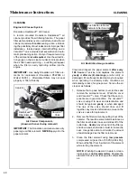
Keep engine air intake screen and cylinder head

fins free of grass clippings, chaff, and dirt.  Inspect
intake screen and cooling fins for cleanliness and
damage.

Check performance of the cooling system by

starting the engine, holding a hand adjacent to the
cylinder head, and feeling the cooling airflow.

Operate the engine at full speed when mowing.

This will allow the engine to produce full horsepower
and move more cooling air through the engine cool-
ing fins.

Air Cleaner

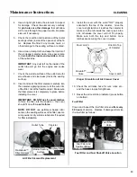
Use only Donaldson air cleaner elements.  After-

market elements may not seal in the air cleaner
housing, allowing dirt to enter the engine. Also, af-
termarket filters often skimp on the filtration media
and require more frequent cleaning and replace-
ment (see instructions below).

Use the air flow restriction gauge to indicate the

need to service the air filter.

DO NOT overservice or frequently “disturb” the

air filter.  A dirty air filter actually cleans better than
a new one.  Changing and cleaning the filter too of-
ten can actually reduce filter efficiency and increase
the opportunity for traces of dust to enter the engine.
Wait until the element really needs servicing as indi-
cated by the loss of engine power.

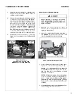
When the air filter element is removed or re-

placed, make sure all dust is cleaned out of the air
cleaner housing and hose.
  Use a damp cloth and
wipe the interior of the canister and hose clean (a
little dirt left here will be sucked into the engine and
reduce engine life). When the filter is reinstalled,
make sure the element is held tight and straight
in the canister for proper seating and sealing.

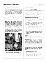
Periodically check the air intake hose for cuts,

nicks, etc., and the hose clamps for tightness.

Oil

DO NOT screw filler cap into crankcase when

checking oil level.

Single viscosity or multi-viscosity oils may be

used with the viscosity matching ambient tempera-
tures for the engine operating conditions.  This will
aid starting in cold weather and assure proper lu-
brication in hot weather.

Use only Kawasaki oil filters.  Aftermarket filters

may not seal properly and/or have the incorrect
pressure relief valve for proper lubrication.

DANGER

Make sure to keep hands clear of exhaust
pipe, muffler, and moving parts when
checking airflow.

Summary of Contents for MS (13 HP)

Page 1: ...y Assembly Operating and Maintenance Instructions Model MS 13 HP Please Read and Save These Instructions Effective Date 01 15 05 For Safety Read All Safety and Operation P N 5000 16 Instructions Prior...

Page 2: ...important to your safety and must be read and understood to help prevent possible injury to the operator or others If anything in this manual is confusing or hard to understand please call our servic...

Page 3: ...allation ________ 17 Deck Discharge Chute Installation ______ 18 Deck Discharge Shield Installation ______ 18 PTO Shaft Guard Installation __________ 18 Tilt Up Roller Wheel Installation ________ 18 M...

Page 4: ...using________ 51 GHS Blower _________________________ 52 GHS Exhaust Screen __________________ 52 Hydrostatic Transmission Cooling Fins __ 53 CHECKING SERVICING _________________ 53 Security of Air Fi...

Page 5: ...ain wheels HYDROSTATIC TRANSMISSION transmits and controls power from the ground drive belt to the main drive wheel LEFT HAND LH refers to the left hand side of the tractor when the operator is seated...

Page 6: ...ese components during the limited war ranty period it is important to find a local authorized servicing agent ofthe componentmanufacturer Any unauthorizedwork doneonthesecomponents dur ing the warrant...

Page 7: ...ection Engine damage could result from insufficient lubrication ELECTRICAL SYSTEM Battery 12 Volt 230 CCA Interstate SP 30 Charging System Flywheel Alternator Charging Output 13 Amp DC Regulated Syste...

Page 8: ...de Drive Clutch and Brake Manual Belt Tightener Clutch and Scrubber Brake Stops Blades within Five 5 Seconds of Disengagement Max Blade Speed 22 in 56 cm Blade 3600 RPM Engine 2900 RPM 16700 FPM 5090...

Page 9: ...r Rotating Blades with a 4 in 10 cm Center Overlap 42 in 107 cm SD Model 22 in 56 cm Two 2 Clockwise Rotating Blades with a 2 in 5 cm Center Overlap 42 in 107 cm GHS Model 22 in 56 cm Two 2 Counter Ro...

Page 10: ...itch Mounted on Grass Delivery Spout Triggers Horn Signal Powerfil Oscillating Delivery Spout Driven by 12 Volt Electric Gearmotor Spreads Material throughout Interior of Catcher 25 Cycles Minute SEAT...

Page 11: ...ass Handling System 6 7 Bushel Catcher Catcher Door Safety Latch Counterweight Spring and Protective Cover NOTE Control Identification shown in Operating Instructions section Deck Support Pin and Heig...

Page 12: ...t Dump Handle Catcher Door Tailwheel Fork and Wheel Fuel Filter Oil Filter Rotating Engine Screen Anti Scuff Rollers Catcher Exhaust Deflector Removable Grass Catcher Screen Not Visible Catcher Door G...

Page 13: ...ransmission RH Transmission Lockout Lever Air Cleaner Air Restriction Indicator Fuel Tank Carburetor GHS Blower Negative Battery Cable Battery Neutral Safety Switch Positive Battery Cable LH Hydrostat...

Page 14: ...ct your authorized Walker Mower Dealer or call Walker Manufacturing Company at 970 221 5614 BEFORE OPERATING 1 Read and understand the contents of this Owner s Manual before starting and operat ing th...

Page 15: ...illed fuel before starting the engine 11 Never attempt to make any adjustments while theengineis running except where spe cifically instructed to do so 12 The electrical system battery contains sulfur...

Page 16: ...th the back door OPEN Dan gerous projectiles may be thrown out of the discharge chute or the back of the grass catcher 17 For GHS equipped models use care when closing the grass catcher door Keep fing...

Page 17: ...to disconnect any safety devices or defeat the purpose of these safety devices 9 Do not change the engine governor settings or overspeed the engine The governor has been factory set for maximum safe...

Page 18: ...d before putting the machine into operation The Decal Part Number is listed below and in the Parts Manual Hydrostat Oil Reservoir 5810 2 Deck Gearbox Cover 5807 3 Underside of Body 5861 Top Rear of Fu...

Page 19: ...nder RH Side 5802 1 Fender LH Side 5802 2 SAFETY CONTROL AND INSTRUCTION DECALS Safety Control and Instruction Decals are installed on the machine if any are missing illegible or damaged a replacement...

Page 20: ...s been shipped wet but the electro lyte level is low or the battery needs to be charged then 1 Fill each battery cell with drinking water to the bottom of the vent wells 2 Charge battery Refer to Batt...

Page 21: ...he post completely to prevent an electrical short Battery Installation Mower Deck Assembly Deck Caster Wheels Installation 1 Remove the bolt nut axle spacer tube and spacer washers from each deck cast...

Page 22: ...ly Attach the deck side discharge shield by positioning the shield hinge lug in front of the deck mount and fastening with two 2 3 8 16 x 1 1 4 in bolts 3 8 16 ESNA nuts and 3 8 in wave spring washers...

Page 23: ...ease alignment of shaft fit shaft end into socket and rotate shaft until the splines line up as indi cated by arrows then slide together 4 If the deck is rear discharge GHS equipped model the rear dis...

Page 24: ...s connected the weight on the deck caster wheels should be 15 to 25 Ib 6 8 to 11 3 kg Check this weight by lift ing on the front of the deck carrier frame If required the spring tension can be adjuste...

Page 25: ...3 Check the front to rear level Rotate the blades to point forward Measure the distance from blade tip to ground on the front and rear The rear of the blade should be 1 8 to 1 4 in 3 to 6 mm higher th...

Page 26: ...Checking Engine Crankcase Oil Level in Maintenance Instructions CHECK AND SERVICE ENGINE AIR CLEAN ER SYSTEM Check air restriction gauge to make sure there is no red indication showing Check conditio...

Page 27: ...e deck to the normal operating posi tion Deck Secured in Tilt Up Position CHECK MOWER BLADE CONDITION SHARP NESS AND SECURITY OF MOUNTING The blade mounting nut should be tightened to 60 ft lb 81 3 N...

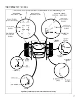
Page 28: ...wise to the O position Engine Choke The choke control lever black knob is located on the left side of the seat To start a cold engine move the choke control forward to the ON position After engine sta...

Page 29: ...which causes the drive wheel for that lever to first slow down stop and then reverse with a full backward lever stroke The levers are released to the FORWARD position for straight ahead ground travel...

Page 30: ...mulated while the ignition switch is in the ON position The hourmeter provides maintenance reminders after certain hours of operation The hourmeter screen will start flashing the reminder one hour pri...

Page 31: ...Drive Wheel Motion Position RIGHT WHEEL STEERING LEVER The Forward Speed Control also Establishes the Neutral Park Position of the Steering Levers FORWARD SPEED CONTROL LEVER FSC Full Forward Ground S...

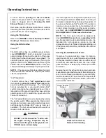
Page 32: ...un smoothly as it warms up As soon as possible move the choke to the OFF position IMPORTANT Make sure the choke is in the OFF position during normal engine operation running with the choke in the ON p...

Page 33: ...he steering levers forward a unique Walker feature always PULL on the levers for steering or for reverse motion of the mower Learn to operate the mower with your left handon the steering levers and ri...

Page 34: ...engaging the blade clutch 2 Push the blade clutch lever SLOWLY back to engage the mower blades IMPORTANT DO NOT engage the blade clutch when transporting the mower across drives side walks loose mate...

Page 35: ...adjusted by positioning the four retainer hitch pins in a series of seven vertical holes on the deck support pins Lift handles have been provided on each end of the deck to assist in raising the deck...

Page 36: ...MENDATIONS FOR MOWING IMPORTANT Operate the engine at full speed when mowing to allow the engine to produce full horsepower and to increase efficiency of the engine cooling system Keep the mower deck...

Page 37: ...arp turns or sudden changes in direction The maximum recommended side slope operating angle is 20 degrees or 33 grade Maximum Recommended Side Slope RECOMMENDATIONS FOR TILT UP DECK OPERATION TRANSPOR...

Page 38: ...y Grass Catcher Catcher Door Spring Catcher Door Exhaust Deflector Exhaust Screen Removable Catcher Door Safety Latch Grass Pak Vane Switch Full Signal Horn Actuator Rod Powerfil Drive Motor Powerfil...

Page 39: ...when using the GHS mower to vacuum leaves it is recommended to raise the front of the mower deck 2 to 3 notches 1 to 1 1 2 in 25 to 38 mm higher than the rear This will avoid bulldozing leaves partic...

Page 40: ...n and free of grass and dirt buildup While some degree of material buildup can be tolerated a point is finally reached where the flow of air and grass clippings is restricted NOTE One condition that q...

Page 41: ...ngine not running opening the catcher back door and triggering the Grass Pak vane by hand as it oscillates The horn should sound as the switch is moved in both directions The full signal horn is desig...

Page 42: ...easing the safety latch on the door hinge mechanism with the right hand The safety latch is released by pressing in on the top of the latch Then the door should close smoothly with the assis tance of...

Page 43: ...and and releasing the safety latch on the door hinge mechanism with the right hand The safety latch is released by pressing in on the top of the latch Then the door should close smoothly with the assi...

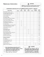
Page 44: ...47 Clean Hydrostatic Transmission Cooling Fins x 53 Clean and Regap Spark Plug x 56 Clean Engine Cooling Fins x 50 Check Fuel Lines and Clamps x 56 Replace Air Filter Element and Vacuator Valve x 48...

Page 45: ...re more frequent cleaning and replace ment see instructions below Use the air flow restriction gauge to indicate the need to service the air filter DO NOT overservice or frequently disturb the air fil...

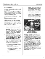
Page 46: ...with the engine running 2 Before removing the dipstick clean the area around the dipstick opening in the engine block to keep any dirt or debris out of the engine 3 Unscrew and remove the filler plug...

Page 47: ...gh the dipstick opening with oil using only crankcase lubricants supplied by the engine manufacturer Refer to Specifica tions in this manual or the engine owner s manual Use the recommended oil viscos...

Page 48: ...6FUXEEHU UDNH LQNDJH 2LO 6 0RGHO 2QO OXWFK FWXDWRU 5RG UHDVH UHDVH 6OLGH UHD 372 HOW 7LJKWHQHU 3LYRW UHDVH QJLQH LSVWLFN 2LO LOOHU 2LO DWFKHU LQJH 3RLQW 2LO 7KURWWOH RQWURO DEOH QGV 2LO KRNH RQWURO D...

Page 49: ...ns LUBRICATION 45 2 3 1 4 10 6 7 6 8 31 13 32 28 33 27 34 15 31 9 27 28 25 29 30 26 26 20 21 9 14 15 11 12 18 16 6 7 6 8 4 2 1 10 11 12 13 22 22 23 23 22 22 24 24 23 24 25 18 19 17 19 5 Chassis and De...

Page 50: ...e completely drained of oil approximately 5 fl oz 15 cl of oil per gearbox is required to refill the gear drive assembly NOTE Since the gearboxes are connected as a unit by connector tubes it is neces...

Page 51: ...eservoir a If a small amount of fluid leaks from around the air bleed plug The transmission is full of fluid Tighten the plug and fill the reservoir to the COLD level mark b If no fluid leaks from aro...

Page 52: ...he element yearly or after six 6 cleanings or when dirty or damaged More frequent cleaning may be required when operating in extremely dusty conditions as indicated by a loss of engine power Service t...

Page 53: ...the cover IMPORTANT DO NOT use the cover latches to force the filter into the canister the cover should fit on with no extra force NOTE DO NOT use petroleum based lubri cants on the sealing surfaces...

Page 54: ...air cooled engine to keep the cylinder head cooling fins clean and free of obstruction After every 8 hours of operation check the performance of the cooling system by starting the engine holding a han...

Page 55: ...aise the deck lock lever handle on each side of the carrier frame and pull out to release carrier frame for tilting action 2 Using the carrier frame lift handle raise deck to the TILT UP position and...

Page 56: ...must spin freely Any binding or drag ging of the wheel is an indication of dirt buildup This buildup must be cleaned to avoid abra sive wear of the blower blades excessive power loss and eventual loss...

Page 57: ...following inspection is only an external inspection and should be done without disturb ing the filtration components On a daily basis visually inspect the external condi tion of the complete air clea...

Page 58: ...ery 10 hours of operation or more often when mowing abrasive type grass or operating on sandy soils Replace blades if worn bent cracked or otherwise damaged refer to REPLACING REPAIRING the Mower Blad...

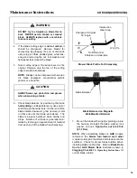
Page 59: ...a blade is generally main tained by removing an equal amount of material from each end of the blade when sharpening Mower Blade Profile For Sharpening Blade Balanced on Magnetic Wall Mounted Balancer...

Page 60: ...tted replace the plug refer to Specifications for the proper type of replacement plug Check the spark plug gap with a wire type feeler gauge and set the gap between 0 028 and 0 032 in 0 7 and 0 8 mm R...

Page 61: ...ive Belts There are three 3 individual belts on the machine Engine Belt PTO Drive Belt Ground Drive Belt The belts may be removed and replaced using the procedures described on the following pages DAN...

Page 62: ...elt off the compound pulley and remove the belt Engine Belt Engaged Engine Belt Disengaged Compound Pulley Idler Pulley Belt Tightener Arm Push Idler Pulley to Relax Belt Engine Pulley Tension Spring...

Page 63: ...er brake without tightening the PTO drive belt Roll belt off PTO drive pulley and GHS blower pulley GHS model only 2 Install the PTO drive belt by reversing the removal procedure Check scrubber brake...

Page 64: ...ax Belt Transmission Drive Pulley Ground Drive Belt Tension Spring Idler Pulley Belt Tightener Arm Hydrostatic Drive Pulley Hydrostatic Drive Pulley Ground Drive Belt Assembly Disengaged 2 Reverse the...

Page 65: ...ear pin to provide shock load protection to the mower deck drive This system provides prima ry shock protection in case of blade impact and will normally shear before the individual shear bolts on the...

Page 66: ...r straightness by marking blade tip position inside the deck housing and then rotating the opposite end of the blade to the same po sition and comparing If the difference in blade tip track is more th...

Page 67: ...tighten the opposite side or loosen the same side to lower the pin Adjustments are made by loos ening the jam nut and tightening or loosening the set screws on the Deck Mount Pivot Brackets Retighten...

Page 68: ...ket and bend it down Adjustments should be done in very small increments check ing the measurement each time until the recom mended measurement is achieved This measurement is applicable to all catche...

Page 69: ...BBBBBBBBBBBBBBBBBBBBBBBBBBBBBBBBBBBBBB BBBBBBBBBBBBBBBBBBBBBBBBBBBBBBBBBBBBBBBBBBBBBBBBBBBBBBBBBBBBBBBBBBBBBBBBBBBBBBBBBBBBBBBBBBBBBBBBBBBBBBBBBBBBBB BBBBBBBBBBBBBBBBBBBBBBBBBBBBBBBBBBBBBBBBBBBBBBBBBB...

Page 70: ...66 Operator s Notes...

Page 71: ...in the Owner s Manual for operation and maintenance B The customer shall pay any charges for making service calls and or for transporting the mower to and from the place where the inspection and or w...

Page 72: ...ar Temperature 50 F o 10 C o Wind Speed 5 mph 8 kmh Humidity 52 Barometric Pressure 24 9 HG 759 mm Hg Lwa 99 OPERATOR LpA 93 Vibration Model MS Vibration Level Vibration levels at the operators handle...

Reviews: