FoldSmart™ Installation and Maintenance Manual
Revision 1 - MAY 2023
41
INSTALLATION ADJUSTMENTS
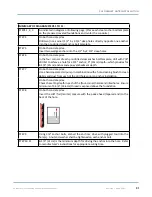
5.
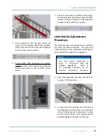
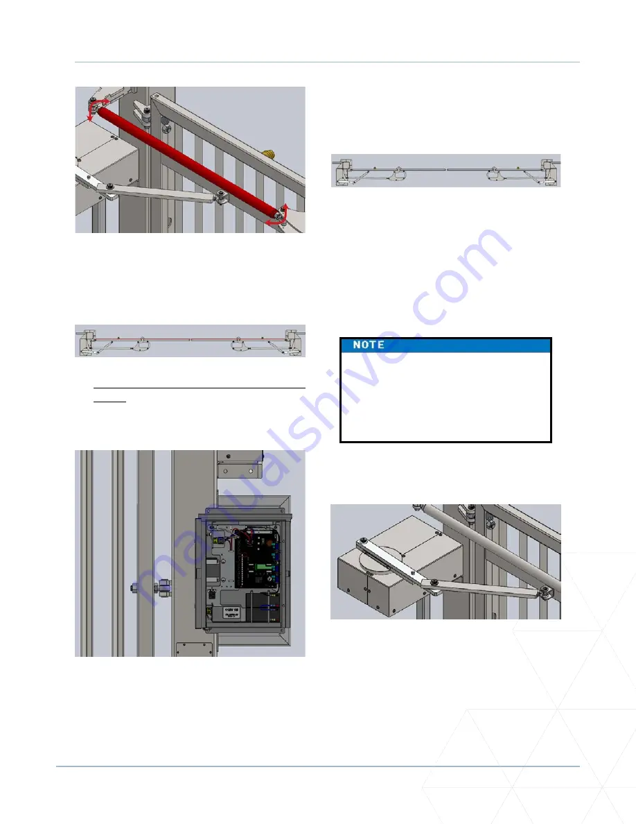
Once adjusted so that the gate panels are
square at a 90-degree angle to the roadway,
tighten the nuts on either end of the drawbar
to lock in the current position.
6.
Ensure traffic, both pedestrian and vehicle,
is clear and then test the gate by pushing the
OPEN push-button on the SmartDC control
board.
7.
Ensure the open limit is suitable and the gate,
when closed, does not bind on the steel vertical
catches. If there is binding, further adjust the
drawbar or limit switches as needed.
Limit Switch Adjustment
Procedure
The FoldSmart gate uses limit switches to identify
the open and closed positions. The open and
closed positions can be modified by adjusting the
point at which the switches are triggered.
2.
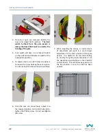
To access the limit switches, first remove the
motor/gearbox housing covers. You will need
a Torx T27 bit to remove the fasteners. If using
a drill or impact driver, set to a slow speed to
avoid damaging the fasteners and/or bit.
The limit switch adjustment is
done in conjunction with the
drawbar adjustment. Refer to
the preceding instruction set for
Drawbar Adjustment Procedure.
1.
Each motor/gearbox assembly will have its
own pair of limit switches.
Summary of Contents for FOLDSMART
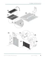
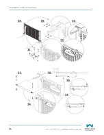
Page 36: ...36 wallaceperimetersecurity com Phone 866 300 1110 FOLDSMART GATE INSTALLATION ...
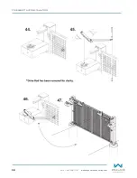
Page 38: ...38 wallaceperimetersecurity com Phone 866 300 1110 FOLDSMART GATE INSTALLATION ...
Page 146: ......
Page 147: ...FoldSmart XT Drawings Generic Site Layout and Options ...
Page 148: ......
Page 149: ......
Page 150: ......
Page 151: ......
Page 152: ......
Page 153: ......
Page 154: ......
Page 155: ......
Page 156: ......
Page 157: ......
Page 158: ......
Page 160: ......

