7
3684A050 Installation Instructions
10.
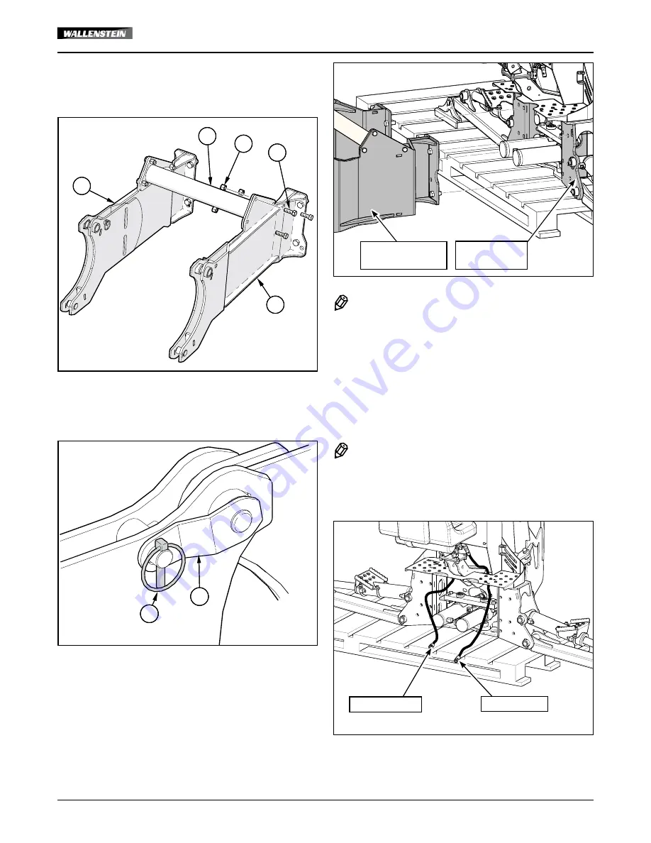
Connect (
3684W080H
) Back Hoe Link, RH (9) to
(
3684W080
) Back Hoe Link, LH (8) with (
3600W603
)
Crossmember (2), using (
Z71515
) 1/2" NC hex bolts (11)
and (
Z72251
) 1/2" NC hex lock nuts (14).
2
9
14
8
11
2
9
14
8
11
11.
Hook the sub frame to the back hoe mount using
(
3600W201
) Subframe Top Pins (1).
Install (
Z12120
) Lynch Pins (10) to hold the Top Pins in
place.
1
10
10
1
12.
Take the backhoe sub-frame mount and attach it to the
backhoe on main base bracket. Use (
Z71617
) 5/8" NC x
1-3/4" Lg bolts (13) and (
Z72261
) 5/8" NC hex lock nuts
(15) — 4 for each left- and right-hand sides. Torque-tighten
the bolts. Refer to the Bolt Torque specification table on the
last page.
Backhoe Main
Base Bracket
Backhoe Mount
Assembly
NOTE:
The sub-frame should remain on your
backhoe and not be removed. Check that
the lift arms move freely with the sub-
frame installed.
13.
Align and reverse the tractor up to the bracket. Get close
enough to attach the hydraulic hoses to the backhoe.
14.
Attach the hydraulic lines from the backhoe to the tractor.
See illustration.
NOTE:
The directional control valve on the
back hoe does not allow reverse flow if
pressure and return lines are connected
incorrectly.
Pressure Line
Return Line


