background image

5.  Controls 

Before operating the machine, be familiar with the location and 
function of the controls.

5.1  Engine Controls

 WARNING!

Before starting the engine, read and understand 

the safety and operating information under 

Engine Operation on page 25

.

IMPORTANT!  For complete information about the engine 
controls, see the engine manufacturer's manual.

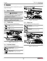
5.1.1  Throttle Lever

The throttle control lever has the following functions:

Fast

Engine speed is fast.

Slow

Engine speed is slow.

02041

Figure  7 – 

Engine throttle control

5.1.2  Fuel Shut-off Valve

The fuel shut-off valve has the following functions:

Fuel shutoff closed

Fuel valve is closed. The engine is off.


Fuel shutoff open

Fuel valve is open. The engine can be started.

02040

Figure  8 – 

Engine fuel shutoff

5.1.3  Choke Lever

The choke control lever has the following functions:

Choke closed

Close the choke to start a cold engine.

Choke open

Open the choke when the engine is warm.

02039

Figure  9 – 

Engine choke control

Controls 

BXMC3409B / BXMC3409B Bundle

Chipper/Shredder

20

Summary of Contents for BXMC3409B

Page 1: ...OPERATOR S MANUAL Chipper Shredder Serial number 1100780 and up BXMC3409B Document Number Z97164_En Rev Aug 2023 BXMC3409B Bundle...

Page 2: ...e 28 6 6 Stop the Machine 28 6 7 Emergency Stop 29 6 8 Set Up the Machine 29 6 9 Operate the Machine 29 6 10 Mulch Collector Bag 31 6 11 Jockey Wheel 32 6 12 Clear a Blockage 33 7 Transport 34 7 1 Tra...

Page 3: ...owing models are covered by this manual Model Features BXMC3409B Chipper shredder with support stand BXMC3409B Bundle Chipper shredder with support stand jockey wheel and mulch collector bag For avail...

Page 4: ...ovince ZIP Postal Code Phone Number Dealer Inspection Checklist Rotor turns freely and the knife clearance is correct Engine starts and runs and fluid levels are correct All cutting edges are sharp an...

Page 5: ...f your Wallenstein product when ordering parts or requesting service or other information The product information plate location is shown in the following illustration Record the model and serial numb...

Page 6: ...t is necessary for safe operation Information labels are usually pictorial with a white background and the number of panels can be different This type of label provides information for the operator or...

Page 7: ...Identifies a hazardous situation that if not avoided could result in minor or moderate injury It can also be used to tell anyone who uses the machine about unsafe practices IMPORTANT Identifies a situ...

Page 8: ...mergency For instructions see Emergency Stop on page 29 Keep a first aid kit available and know how to use the contents of it Keep a fire extinguisher available and know how to use it Wear the appropr...

Page 9: ...e Condition References are made to safe condition throughout this manual Safe condition means putting the machine in a state that makes it safe to service or maintain Before starting any service or ma...

Page 10: ...sign off form can be used to record the completed training The design and manufacture of this product conforms to the applicable provisions in the following standards IISO 4254 1 2013 Agricultural ma...

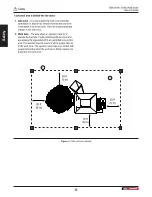
Page 11: ...ions for safe operation of the machine Keep bystanders and workers safe from hazards Obey the following guidelines Use safety cones to identify the work zone perimeter The work zone perimeter should b...

Page 12: ...perator must be to operate the machine People assisting with the work who are wearing the appropriate PPE are permitted to be in this area The operator must be aware of all the people who are in the w...

Page 13: ...n what the safety labels mean and know the safety hazards A safety label can be vertical or horizontal Vertical safety labels have a top panel and a bottom panel Horizontal safety labels have a left s...

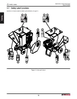
Page 14: ...3 7 3 3 7 3 5 2 6 4 Figure 3 Safety sign locations 3 1 Safety Label Locations Numbers correspond with the Safety Label Definitions on page 15 Safety Labels BXMC3409B BXMC3409B Bundle Chipper Shredder...

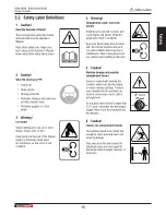
Page 15: ...nd hands Install the guard when work is complete Keep your hands away from the drive belt Turn off the machine and put it in a safe condition before service or maintenance Wear heavy gloves and use ca...

Page 16: ...replaced Requirements The installation area must be clean and dry The application surface must be clean and free of grease or oil The ambient temperature must be above 50 F 10 C A squeegee plastic ban...

Page 17: ...use the machine They can endanger themselves and others or damage property 4 2 Training Each operator must be trained in the correct operating procedures before using the machine 1 Review control loca...

Page 18: ...lever 2 Shredder hopper 3 Shredder gate 4 Handles 5 Chipper hopper 6 Twig breaker 7 Ledger knife 8 Operator s manual tube 9 Discharge chute 10 Tires 1 of 2 11 Clutch lever 12 Engine 13 Support stand 1...

Page 19: ...chine components continued 1 Rotor knife 2 Rotor 3 Shredder plate 4 Shredder knives 5 Brake clutch 6 Drive belt 7 Drive belt guard 8 Chop block 9 Upper rotor housing BXMC3409B BXMC3409B Bundle Chipper...

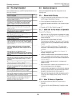
Page 20: ...wing functions Fast Engine speed is fast Slow Engine speed is slow 02041 Figure 7 Engine throttle control 5 1 2 Fuel Shut off Valve The fuel shut off valve has the following functions Fuel shutoff clo...

Page 21: ...nd start the engine 02042 Figure 10 Starter cord 5 2 Shredder Gate Lever The shredder has a spring loaded gate Open the gate Push down on the lever The gate opens and material in the shredder hopper f...

Page 22: ...onds for the rotor to come to a full stop after you move the clutch handle to the STOP position Spring tension holds the clutch handle in the STOP position until the operator moves is to the START pos...

Page 23: ...ual before you start the machine Review all safety information annually Park the machine in a clear location on dry level ground Do not operate the machine on a hillside or area that is cluttered wet...

Page 24: ...ure that there are no bystanders inside the work zone and the spotter is not near a hazard For zone definitions see Work Site on page 11 6 3 Machine Break In Before and during the first eight hours of...

Page 25: ...al Only operate the engine in a location that has good air flow Engine exhaust gases contain carbon monoxide an odorless gas that can cause asphyxiation Do not put your hands or feet near moving parts...

Page 26: ...emaining fuel dries before you start the engine After refueling make sure that the fuel cap is tight 6 4 3 Check the Engine Fuel Level CAUTION Check the fuel level outdoors or in an area where there i...

Page 27: ...wait until any remaining fuel dries before you start the engine 7 Install the fuel cap and make sure that it is tight 6 4 5 Check the Engine Oil Level IMPORTANT For more information about engine oil...

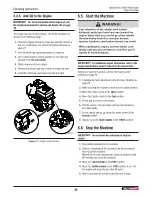
Page 28: ...oid kickback W102 IMPORTANT For additional engine information refer to the engine manufacturer owner s manual in the manual tube Before you start the machine see the information under Controls on page...

Page 29: ...en remove the key from the ignition 4 Make sure that the chipper and shredder hoppers are free of debris 6 9 Operate the Machine WARNING Wear the personal protective equipment PPE that is required to...

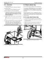
Page 30: ...page 33 Maximum material diameter Chipper hopper 3 7 5 cm Shredder hopper 3 4 1 9 cm 6 9 1 Chip Wood Delimb branches that are larger than 1 2 5 cm in diameter before you put them into the chipper hop...

Page 31: ...eed before continuing Figure 19 Operate the shredder 6 10 Mulch Collector Bag A mulch collector bag can be attached to the discharge chute If you purchased a BXMC3409B Bundle the mulch collector bag i...

Page 32: ...bag 6 11 Jockey Wheel A jockey wheel can be installed on the front of the machine If you purchased a BXC3409B Bundle the jockey wheel is included with your machine To purchase a jockey wheel separatel...

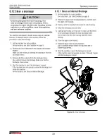
Page 33: ...ge is cleared If the machine does not operate remove the blockage from inside the machine For instructions see Clear an Internal Blockage 6 12 1 Clear an Internal Blockage 1 Set the machine to a safe...

Page 34: ...hine After the machine is prepared for transport complete a circle check to make sure that everything is safe 7 2 Use the Handles IMPORTANT Turn off the engine before moving or tilting the machine Til...

Page 35: ...on page 28 2 Park the machine near the tow vehicle hitch 3 Remove the snap pin from the base of the jockey wheel handle 4 Lower the jockey wheel handle and align the holes in the handle with the tow v...

Page 36: ...all material from the machine 3 Remove the mulch collector bag if installed Clean it and store in a dry location 4 Clean the machine For instructions see Clean the Machine on page 52 5 Start the mach...

Page 37: ...the Machine on page 28 2 Wait for the engine and fluids to cool 3 Remove the current fuel from the engine Operate the machine until the fuel tank is empty or drain the fuel tank and properly dispose...

Page 38: ...l moving parts to stop 3 Disconnect the engine spark plug wire and keep it away from the spark plug Follow good shop practices Keep the work area clean and dry Ground electrical outlets and tools Have...

Page 39: ...elow 40 F 4 C the use of SAE 30 results in hard starting B 10W 30 Above 80 F 27 C the use of 10W 30 may cause increased oil consumption Check the oil level frequently C 5W 30 D Synthetic 5W 30 E Vangu...

Page 40: ...sharpness See page 47 Check the ledger knife sharpness See page 48 Check the shredder knife sharpness See page 50 Check the twig breaker for damage See page 51 Check drive belt alignment See page 44 G...

Page 41: ...nnually Use a hand held grease gun for all greasing Apply one pump per location Wipe each grease fitting with a clean cloth before greasing to avoid injecting dirt and grit Replace or repair broken fi...

Page 42: ...ine with any guards or shields removed The machine is shown here with guards and or shields removed for illustrative purposes only W001 9 6 1 Replace the Drive Belt IMPORTANT After the drive belt is r...

Page 43: ...set the drive belt tension If the drive belt tension is not correct continue with the following steps to set the drive belt tension 3 Loosen do not remove the four bolts that attach the engine mount t...

Page 44: ...lt and the alignment tool are not the same along the length of the drive belt continue with the following steps to align the drive belt 4 Measure the distance between the drive belt and the alignment...

Page 45: ...alignment is correct continue with step 5 If the belt alignment is not correct do steps 2 through 4 again 5 Tighten the four engine mount bolts 6 Do steps 3 and 4 again 7 Do one of the following If t...

Page 46: ...t alignment is correct continue with step 9 If the belt alignment is not correct do steps 6 through 8 9 Remove the sheave bolts from the puller holes Turn them counterclockwise in 1 4 turn increments...

Page 47: ...4 Prevent the rotor from turning Make sure that the rotor cannot move 5 Remove the rotor knife fasteners 6 Carefully remove the rotor knife 7 Clean the rotor knife recess 8 Do one of the following If...

Page 48: ...1 CAUTION Avoid reaching into the rotor housing The rotor and ledger knives are very sharp If it is necessary to reach into the rotor housing set the machine to a safe condition wear heavy gloves and...

Page 49: ...urn the rotor to align a rotor knife with the ledger knife Select the rotor knife that has the least space between the rotor knife and the ledger knife 4 Loosen the ledger knife fasteners 5 Do one of...

Page 50: ...instructions see Stop the Machine on page 28 2 Remove the fasteners and open the upper rotor housing 3 Turn the rotor to access one of the shredder knives 4 Loosen the bolt that holds the set of shre...

Page 51: ...for damage on a regular basis Replace a chop block that has cut broken or bent teeth The chop block can be reversed when dull 00263 Figure 42 Chop block on upper rotor housing 9 11 Twig Breaker Maint...

Page 52: ...n the Machine IMPORTANT Using harsh chemicals can damage the machine finish Do not use gasoline diesel fuel or thinners for cleaning IMPORTANT A pressure washer can damage the machine s product identi...

Page 53: ...s incorrect Check the rotor and ledger knives Rotate sharpen or replace the knives as necessary See page 47 and page 48 The rotor knife angle is incorrect Sharpen the rotor knives to the specified 45...

Page 54: ...e page 47 There is a problem with the engine See the engine manufacturer s manual Noisy drive belt or premature wear on the drive belt The drive belt is loose or worn Inspect the drive belt Adjust the...

Page 55: ...ion Hardened tool steel Rotor diameter 16 in 406 mm Rotor weight 40 lb 18 2 kg Shredder hood opening 3 1 2 x 5 in 9 x 13 cm Shredder material maximum diameter 3 4 in 19 mm Chipper hood opening 6 x 7 i...

Page 56: ...eck the bolt tightness periodically Imperial Bolt Torque Specifications Bolt Diameter Torque SAE Gr 2 SAE Gr 5 SAE Gr 8 lbf ft N m lbf ft N m lbf ft N m 1 4 inch 6 8 9 12 12 17 5 16 inch 10 13 19 25 2...

Page 57: ...does not cover the following 1 Normal maintenance or adjustments 2 Normal replacement of wearable and service parts 3 Consequen al damage indirect damage or loss of pro ts 4 Damages resul ng from Mis...

Page 58: ...on 17 To the new operator 17 Fuel engine Add fuel 27 Check the fuel level 26 Replace the fuel 37 G Grease Points 41 I Inspection checklist dealer 4 Introduction 3 J Jockey wheel 32 L Labels Informatio...

Page 59: ...e 49 Lubricants 39 Maintenance schedule 40 Replace the drive belt 42 Rotor knife maintenance 47 Service and maintenance safety 38 Set the drive belt tension 43 Shredder knife maintenance 50 Replace a...

Page 60: ...WallensteinEquipment com...

Reviews: