background image

7.5  Trailer Jack

 WARNING!

Do not pull the pin out of a trailer jack when there 

is weight on the jack. The machine can move 

unexpectedly and cause minor to severe injuries. 

Attach the machine to a tow vehicle or put blocks 

under the trailer tongue to hold the weight before 

you remove the pin from a trailer jack.

The trailer jack has two functions. It supports the machine when 
it is not attached to a tow vehicle or helps to keep the machine 
stable when it is attached to a tow vehicle.

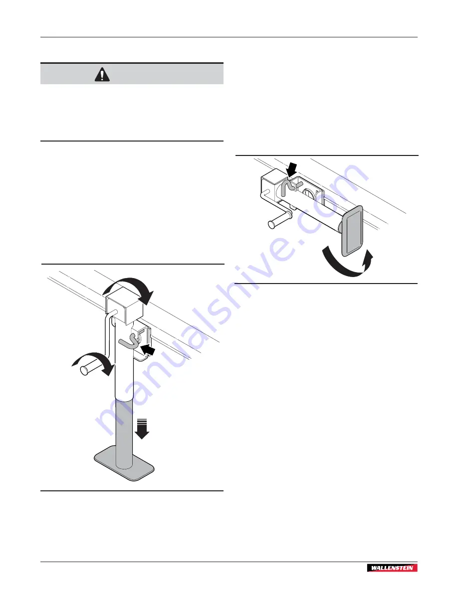
7.5.1  Lower the Trailer Jack

1. 

Pull the pin out of the bracket.

2. 

Turn the trailer jack to the vertical position.

3. 

Insert the pin through the bracket to hold the trailer jack in 
the vertical position.

4. 

Turn the handle clockwise to lower the base.

01782

01782

Figure  28 – 

Trailer jack in the lowered position

7.5.2  Stow the Trailer Jack

1. 

Support the machine to remove weight from the trailer jack. 
Attach the machine to a tow vehicle or support the trailer 
tongue with blocks.

2. 

Turn the handle counterclockwise to retract the base.

3. 

Pull the pin out of the bracket.

4. 

Turn the trailer jack to the horizontal position.

5. 

Insert the pin through the bracket to hold the trailer jack in 
the horizontal position.

01782

01782

Figure  29 – 

Trailer jack in the stowed position

Transport

BXT36S 

Wood Chipper

40

Summary of Contents for BXT36S

Page 1: ...OPERATOR S MANUAL Wood Chipper Serial numbers 1101388 and up BXT36S Document Number Z97162_En Rev Oct 2023...

Page 2: ...achine 31 6 7 Emergency Stop 31 6 8 Set Up the Machine 31 6 9 Operate the Wood Chipper 33 6 10 Remove a Blockage 34 6 11 Rotor Safety 36 7 Transport 37 7 1 Transport Safety 37 7 2 Prepare the Machine...

Page 3: ...ses or maintains the machine must read and understand the safety operation and maintenance information in this manual and the engine manufacturer s manual For information about the accessories go to W...

Page 4: ...arge chute and deflector move freely All belts are aligned and the tension is correct All fasteners are torqued to the correct specifications All grease points are lubricated Engine clutch and rotor s...

Page 5: ...when you order parts or request service or other information The product information plate location is shown in the following illustration 02270 Figure 1 Product information plate location Record the...

Page 6: ...ation Information labels are usually pictorial with a white background and the number of panels can be different This type of gives information to the operator or shows the operation of a control Prod...

Page 7: ...tices CAUTION Identifies a hazardous situation that if not avoided could result in minor or moderate injury It can also be used to tell anyone who uses the machine about unsafe practices IMPORTANT Ide...

Page 8: ...y For instructions see Emergency Stop on page 31 Keep a first aid kit available and know how to use the contents of it Keep a fire extinguisher available and know how to use it Wear the appropriate PP...

Page 9: ...s it safe to service or maintain Before you start any service or maintenance do the following SAFE CONDITION 1 If the machine is connected to a tow vehicle set the tow vehicle s parking brake stop the...

Page 10: ...gn off form can be used to record the completed training The design and manufacture of this product conforms to the applicable provisions in the following standards ISO 4254 1 2013 Agricultural machin...

Page 11: ...operation of the machine Keep bystanders and workers safe from hazards Obey the following guidelines Use safety cones to identify the work zone perimeter The work zone perimeter should be a minimum of...

Page 12: ...afe zone 2 Work Zone The work zone is the area where the operator must be to operate the machine People who are helping with the work and wearing the necessary PPE can be in this zone The operator mus...

Page 13: ...safety labels are available from your local Wallenstein Equipment dealer or distributor Keep the safety labels clean and legible at all times When a part that has a safety label on it is replaced the...

Page 14: ...Figure 3 Safety label locations rear 3 2 Safety Label Locations The numbers correspond with the Safety Label Definitions on page 16 02243 4 1 2 2 1 5 3 Safety Labels BXT36S Wood Chipper Safety 14...

Page 15: ...02244 4 5 1 1 6 7 8 7 9 10 11 9 1 2 Figure 4 Safety label locations front Safety Labels BXT36S Wood Chipper Safety 15...

Page 16: ...alifornia USA to comply with Proposition 65 the Safe Drinking Water and Toxic Enforcement Act of 1986 4 Caution Wear the necessary PPE For example A hard hat Heavy gloves Hearing protection Protective...

Page 17: ...plosion hazard Attempting to charge a frozen battery can cause it to explode An explosion can cause serious injury or death from projectiles extreme heat chemicals and loud noise Warm the battery to a...

Page 18: ...ty instructions Only a fully trained operator is approved to use the machine A person who operates the machine without the correct training is a danger to themselves and others and can cause property...

Page 19: ...front view 1 Upper rotor housing 2 Rotor knife 3 Drive belt 4 Rotor sheave 5 Operator s Manual storage tube 6 Drive belt guard 7 Battery 8 Front guard 9 Trailer jack 10 Safety chains 11 Ball mount hi...

Page 20: ...harge chute 3 Deflector 4 Engine guard 5 Rotor lock 6 Tires one of two 7 Ledger knife clearance gauge 8 Ledger knife 9 Chipper hopper 10 Emergency stop button E stop 11 Rotor Figure 7 Machine componen...

Page 21: ...he emergency stop is off The machine can operate On The emergency stop is on the button is pressed The machine cannot operate To reset turn off the emergency stop button turn the button clockwise and...

Page 22: ...o a person who is not trained in the correct operation Always remove the key and keep it in a safe location to prevent an unauthorized person from starting the engine IMPORTANT Long start cycles can r...

Page 23: ...igure 12 Rewind start control 5 3 Discharge Chute The discharge chute directs the wood chips in the selected direction The discharge chute can be turned 284 The latch handle pin holds the discharge ch...

Page 24: ...urn them clockwise 01337 Figure 14 Deflector 5 5 Rotor Lock WARNING Engage the rotor lock when the upper rotor housing is open to prevent the rotor from moving unintentionally Failure to engage the ro...

Page 25: ...hine Review all safety information annually Park the machine in a clear location on dry level ground Do not operate the machine on a hillside or area that is cluttered wet muddy or icy to prevent slip...

Page 26: ...e tire for the correct air pressure Make sure that all the fasteners are installed and torqued to the correct specifications For more information see Bolt Torque on page 65 and Lug Nut Torque on page...

Page 27: ...inder fins and engine shrouds free of debris to prevent the engine from overheating Keep the engine free of wood chips and other debris that can affect the engine speed Use fresh fuel less than three...

Page 28: ...ank Do not overfill the fuel tank Carefully remove any spilled fuel and then wait until any remaining fuel dries before you start the engine After you add fuel to the tank make sure that the fuel cap...

Page 29: ...gine 7 Install the fuel cap and make sure that it is tight 6 4 5 Check the Engine Oil Level IMPORTANT For more information about engine oil see the engine manufacturer s manual and Engine Oil on page...

Page 30: ...bruises sprains fractures and broken bones can result When you start the engine pull the starter cord slowly until you feel resistance and then pull it rapidly to avoid kickback W102 IMPORTANT If the...

Page 31: ...te to a dangerous level even in an area with good air flow W006 For more information see Figure 20 on page 32 1 Select a work site and set up a safe work area For more information see Work Site on pag...

Page 32: ...02251 Figure 20 Set up the machine Operating Instructions BXT36S Wood Chipper 32...

Page 33: ...eing blown out of the chipper hopper The machine can release wood chips fast enough to cause personal injury and property damage Figure 21 Operate the wood chipper 6 9 1 Prepare the Material Cut large...

Page 34: ...or will draw the material into the machine Do not attempt to force the material into the rotor housing 6 10 Remove a Blockage WARNING Put the machine in a safe condition before you remove a blockage D...

Page 35: ...urn the rotor to make sure that there is not a blockage between the rotor and ledger knife Do not reach into the rotor housing while the rotor is moving c Engage the rotor lock For instructions see En...

Page 36: ...housing 4 Pull the rotor lock pin toward you turn it clockwise 90 degrees and hold it away from the rotor Make sure that the latch pin is in the horizontal slot 5 Slowly and carefully turn the rotor...

Page 37: ...wheel rims for damage and torque the wheel lug nuts to the correct specifications For more information see Lug Nut Torque on page 66 Examine the tires for cuts or damage Make sure that the tires are f...

Page 38: ...02249 Figure 26 Transport position Transport BXT36S Wood Chipper 38...

Page 39: ...40 9 Cross the two safety chains below the trailer tongue and then attach them to the tow vehicle one on each side of the ball mount hitch 01230 Figure 27 Ball mount hitch connection 7 4 Disconnect f...

Page 40: ...bracket 2 Turn the trailer jack to the vertical position 3 Insert the pin through the bracket to hold the trailer jack in the vertical position 4 Turn the handle clockwise to lower the base 01782 017...

Page 41: ...ernal components Replace or repair any worn or damaged components 7 Paint scratches and dents to prevent rust 8 Do one of the following If the machine will be in storage for one to three months add st...

Page 42: ...02250 Figure 30 Storage position Storage BXT36S Wood Chipper 42...

Page 43: ...to the engine outdoors or in an area that has good air flow 1 Stop the machine For instructions see Stop the Machine on page 31 2 Wait for the engine and fluids to cool 3 Remove the current fuel from...

Page 44: ...ry terminal and keep it away from the battery 5 Remove all material from the chipper hopper 6 Wait until the engine and machine are cool Follow good shop practices Keep the work area clean and dry Gro...

Page 45: ...hard starting B 10W 30 Above 80 F 27 C the use of 10W 30 may cause increased oil consumption Check the oil level frequently C 5W 30 D Synthetic 5W 30 E Vanguard Synthetic 15W 50 9 2 3 Engine Fuel For...

Page 46: ...or knife ledger knife and twig breaker sharpness See page 57 Check the battery condition See page 51 Lubricate pivot points and hinges See page 49 Grease the machine See page 48 Check the drive belt t...

Page 47: ...an each grease fitting before you apply grease This prevents grease and dirt from getting inside the component Use a hand held grease gun to apply one pump of grease to each grease point If a grease f...

Page 48: ...ons Item Location Frequency Number of Locations 1 Rotor shaft bearings 50 hours or annually 2 2 Wheel bearings 50 hours or annually 2 1 2 1 02252 Figure 31 Grease fitting locations Service and Mainten...

Page 49: ...rust prevention oil to the following locations 1 4 2 3 02253 Figure 32 Hinge and pivot point grease locations Item Location Frequency Number of Locations 1 Deflector 50 hours or annually 2 2 Trailer...

Page 50: ...es and fittings frequently for cracks or leaks Replace fuel lines or fittings that are damaged Store fuel away from all wood material Do not check for a spark with the spark plug or spark plug wire re...

Page 51: ...use serious injury or death from heat impact and chemical hazards Keep all sparks and flames away from batteries Electrolyte fumes are explosive Do not jump start a frozen battery The battery can expl...

Page 52: ...e battery and the battery charger For more information and instructions contact the battery manufacturer and battery charger manufacturer 1 Remove the battery from the machine For instructions see Rem...

Page 53: ...ve belt guard fasteners and the guard 3 Loosen do not remove the four bolts that attach the engine mount to the machine frame See Figure 39 on page 54 4 Turn the drive belt tensioning bolts to move th...

Page 54: ...steps to set the drive belt tension 3 Loosen do not remove the four bolts that attach the engine mount to the machine frame See Figure 39 4 Use the drive belt tensioning bolts to set the drive belt te...

Page 55: ...1 For instructions see Align the Engine Clutch 3 Do steps 1 and 2 again to make sure the drive belt is aligned 02259 1 3 4 2 Figure 40 Check the drive belt alignment 1 Clutch flywheel 2 Point of align...

Page 56: ...alignment is correct continue with step 9 If the belt alignment is not correct do steps 6 to 8 9 Remove the sheave bolts from the puller holes Turn them counterclockwise in 1 4 turn increments 10 Ins...

Page 57: ...om turning Make sure that the rotor cannot move For instructions see Engage the Rotor Lock on page 36 6 Remove the rotor knife fasteners 7 Carefully remove the rotor knife 8 Clean the rotor knife rece...

Page 58: ...e rotor housing The rotor and ledger knives are very sharp If it is necessary to reach into the rotor housing set the machine to a safe condition wear heavy gloves and be very cautious W003 9 10 1 Rep...

Page 59: ...with the ledger knife Select the rotor knife with the smallest space between the rotor knife and the ledger knife 5 Loosen the ledger knife fasteners 6 Do one of the following Insert a ledger knife c...

Page 60: ...ft 45 N m 02274 Figure 49 Install a twig breaker 9 12 Clean the Machine IMPORTANT Do not use gasoline diesel fuel or thinners for cleaning Harsh chemicals can damage the machine finish IMPORTANT Do no...

Page 61: ...pper It prevents wood chips from blowing out of the chipper hopper Do not use the machine without the safety curtain installed Use the following procedure to replace the safety curtain 1 Set the machi...

Page 62: ...gle is incorrect Sharpen the rotor knives to the specified 45 angle and check that the knives are installed correctly For instructions see page 58 The discharge chute is blocked Remove all material fr...

Page 63: ...57 and page 58 There is a problem with the engine See the engine manufacturer s manual The drive belt is noisy or there is premature wear The drive belt is loose worn or the tension is too tight Exami...

Page 64: ...otor diameter 25 64 cm Rotor weight 145 lb 66 kg Discharge chute height 62 157 cm Discharge chute rotation 284 Drive system Centrifugal clutch and drive belt Engine speed 3 600 RPM Rotor speed 1 620 R...

Page 65: ...ndicated Check the bolt tightness periodically Imperial Bolt Torque Specifications Bolt Diameter Torque SAE Gr 2 SAE Gr 5 SAE Gr 8 lbf ft N m lbf ft N m lbf ft N m 1 4 inch 6 8 9 12 12 17 5 16 inch 10...

Page 66: ...r the first 10 miles 16 km 25 miles 40 km and 50 miles 80 km Check the lug nut torque periodically thereafter Start all lug nuts onto the threads by hand Tighten lug nuts in stages following the patte...

Page 67: ...his warranty does not cover the following 1 Normal maintenance or adjustments 2 Normal replacement of wearable and service parts 3 Consequen al damage indirect damage or loss of pro ts 4 Damages resul...

Page 68: ...50 Engine maintenance 50 Engine maintenance safety 50 Engine specifications 64 Replace the engine fuel 43 Engine controls 21 Engine operation 27 Equipment safety guidelines 9 F Familiarization 18 Mac...

Page 69: ...e and maintenance safety 44 Signal words 7 Storage safety 41 Tire safety 52 Transport safety 37 Work site 11 Safety curtain 61 Safety curtain maintenance 61 Safety labels 13 Replace a safety label 13...

Page 70: ...ansport safety 37 Troubleshooting 62 Twig breaker 20 Twig breaker maintenance 60 Types of labels on the machine 6 W Warranty 67 Activate the warranty 4 Work site 11 Example of a safe work area 12 Inde...

Page 71: ......

Page 72: ...WallensteinEquipment com...

Reviews: