Total Extension Cord Length (feet)
Cord Size (AWG)
25
16
50
12
100
10
150
8
200
6
Unpacking
Carefully remove the tool and all loose items from the shipping container. Retain all packing materials
until after you have inspected and satisfactorily operated the machine.
Carton Contents
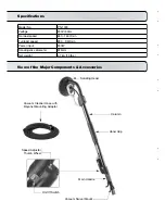
1. Power sander
2. Vacuum cleaner hose
3. Instruction manual
DO NOT OPERATE THIS TOOL UNTIL YOU READ AND UNDERSTAND THE ENTIRE
INSTRUCTION MANUAL
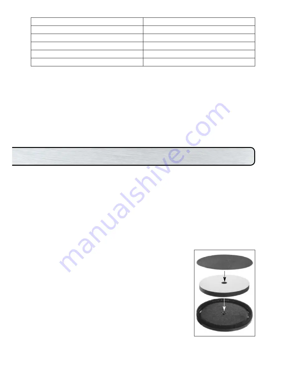
To install a sandpaper disc:
1. Unplug the machine.
2. Peel away the worn out sandpaper disc, leaving the sponge backing pad in place.
3. Carefully center the new sandpaper disc and press into place. It will be held securely by the hook
and loop backing.
To replace the Hook and Loop Sponge Pad:
The sponge pad must be perfectly flat to get good sanding results. If it is deformed or damaged it will
cause very uneven sanding. Always replace it when damaged. It is hook and loop on both sides, so
to replace it, peel it away from the hook and loop on the Sanding Plate Base and, taking great care to
keep it perfectly centered, affix a new one.
The Brush Bristles on the edge of the Sanding Plate Cover:
The brush bristles on the edge of the Sanding Plate Cover serve two
purposes, they keep the sanding disc properly aligned with the work
surface without gouging and they also help the efficiency of the dust
collection by the vacuum cleaner. These brush bristles will wear with
continued use.
The Sanding Plate Cover should be replaced when the bristles are too worn
to ensure effective dust collection and stabilization of the sanding head.
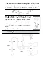
To replace, hold the center bolt from turning with a slothead screwdriver
and unscrew the sanding plate. Then, using snap-ring pliers, remove the
circlip which holds the sanding plate cover to the bracket. Remove the
vacuum hose and lift sanding plate cover away.
Replacement is the opposite of removal. Entrust all repairs to an
authorized service center.
NOTE: Only use sandpaper discs which fit properly and which are designed for vacuum use.
Instructions
Summary of Contents for PS-1000
Page 1: ...OPERATING INSTRUCTIONS POWER SANDER model PS 1000...
Page 10: ...PS 1000 Exploded View...
Page 13: ......
Page 14: ...CUSTOMER SERVICE 1300 653 177...


