background image

12

EN

INSTRUCTIONS FOR USE AND RECOMMENDATIONS FOR A CORRECT APPLICATION 

Mix the paint product according to the technical data sheets of the products to be used. 
Filter the product before its use. 
Choose the size of the needle (

A

) / nozzle (

U

) / cap (

C

) kit depending on the product to be sprayed and the speed of 

desired job. For a precise indication of the spray gun set-up please refer to the main paint manufacturers’ specifications, by 
visiting the website www.walmec.com/solution finder, or simply scan the 

QR code below (*)

For Slim Kombat and Slim Xlight models, before using the spray gun, check if the removable diffuser (

D

) is properly installed. 

Tighten the nozzle (

U

) to the gun body (

K

) with a hand tightening torque device, set not less than 14 Nm. 

Verify that all the components are properly installed and tightened. 
Check the correct positioning of the cap (

C

) (vertical fan spray/horizontal fan spray): it must be “adequately locked” after 

the ring nut (

Cg

) has been tightened. 

“Fully open” product adjustment: pull the lever (

L

) completely back, and screw the needle-adjusting handwheel (

R

to the position where the lever begins to move. 
“Fully open” fan spray pattern adjustment: completely unscrew the jet adjusting handwheel (

G

). 

“Fully open” air flow adjustment: for models equipped with a flow rate adjuster (

P

), unscrew the flow-regulator handwheel 

completely (

P

). 

Fasten the color filter in its position, and fix/screw the cup to the spray gun’s product inlet (

E

), having previously filled it 

with the painting product to be used.  
Connect the spray gun to the compressed air supply (

I

). If possible, use an air pipe with a minimum section diameter equal 

to 10 mm (0.37”). 
If quick connect air couplings are required, use only high pressure/high flow elements: other coupling types do not allow 
an adequate and stable air flow for the proper use of the air gun. 
Make sure that the compressed air used is perfectly filtered from water, oil, and other impurities (for example with the 
installation of the Walcom FSRD3/4 filter unit, or the more efficient and complete TD

3

/TD

1

 PRO multifunctional filter and 

thermal conditioner unit). 
Pulling  back  the  lever  (

L

)  to  the  “1st  phase”  position,  that  is  without  releasing  the  paint  product,  adjust  the  air  supply 

pressure according to the most suitable pressure indications. If the spray gun works with less than ideal pressures, optimal 
finishes will not be obtained. 
Fine tune and adjust the shape of the fan spray, if necessary, by performing the following steps: 
- adjust the air pressure preferably by acting on the regulator/meter (

M

) and/or (

P

); 

- adjust the quantity of the product discharge, by acting on the needle-adjusting handwheel (

R

): turning it clockwise redu-

ces the quantity of product dispensed; 
- adjust the fan spray by acting on the jet adjusting handwheel (

G

): turning it clockwise reduces the height of the fan spray 

area. 
To  paint,  pull  back  the  lever  (

L

)  completely  and  maneuver  the  spray  gun  so  that  the  jet  is  always  perpendicular  to  the 

surface to be painted, at the recommended painting distance for the model in use. 
It is always preferable to apply paint with horizontal movements and with the most uniform speed possible, overlapping at 
least 50% of each spray passage. Any displacements of the structure during the emission of the paint product can cause 
an uneven application of the paint layer.

When  painting

,  for  models  equipped  with  a  quick  connect/release  pressure  gauge  (

Z

),  and  after  adjusting  the  system 

appropriately, 

always disconnect

 the quick-release pressure gauge (

Z

) from its corresponding coupling (

I

).

Always disconnect or close the air supply, limiting the pressure, when the spray gun is not used.

1 -


2 -


3 -


4 -


5 -


6 -


7 -


8 -


9 -


10 -


11 -


12 -


13 -


14 -


15 -


16 -


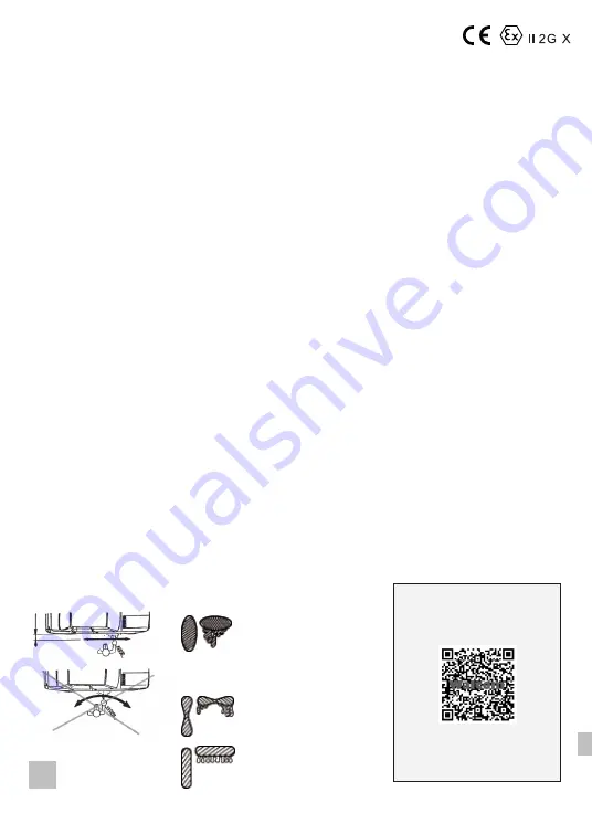
SHAPE OF THE FAN SPRAY
Vertical Fan Spray Pattern

SHAPE OF THE FAN SPRAY
Horizontal Fan Spray Pattern

- Air pressure too low
- Product viscosity too high
- Quantity of product too high

- Air pressure too high
- Product viscosity too low
- Quantity of product too low

- Regular jet

CORRECT APPLICATION

CORRECT SPRAY GUN SETUP 
BY MANUFACTURER - PAINT 
CHARTS  

Check the correct setup 
of the  spray gun here, 
or visit 
www.walmec.com/solution finder  

(*)

Summary of Contents for Walcom GENESI CARBONIO 360 EVO HALO BASE

Page 1: ...LP GEO GENESI ALLUMINIO HALO Base HALO Clear HVLP GEO SLIM KOMBAT HALO HALO SR HVLP SLIM XLIGHT SLIM XLIGHT HD HALO HALO SR HVLP SLIM SLIM HD HALO HALO SR HVLP EGO CARBONIO HALO HVLP EGO HALO HVLP AER...

Page 2: ...2...

Page 3: ...efahr Risque d incendie Peligro de incendio Perigo de inc ndio Pericolo ustioni Burn hazard Verbrennungsgefahr Risque de br lure Peligro de quemaduras Risco de queimadura Pericolo esplosione Explosion...

Page 4: ...nato esclusivamente da personale qualificato ed addestrato Il maneggio dell aerografo vietato a persone la cui capacit di reagire ridotta da droghe alcol farmaci o in altra maniera Mettere l aerografo...

Page 5: ...pulizia asciugare e soffiare con aria compressa pulita la pistola l ugello il cappello e il serbatoio Non utilizzare oggetti metallici o comunque particolari che possano danneggiare i fori dell ugell...

Page 6: ...iltrante Walcom FSRD3 4 oppure della pi completa ed efficiente unit filtrante e termo condizionatrice polifunzionale Walcom TD3 TD1 PRO Tirando la leva L nel primo tempo ovvero senza fare uscire prodo...

Page 7: ...7 IT E G R K I P L Cg C M E D C U E G A R K I P L Cg M E GENESICARBONIO360EVO V Z M I...

Page 8: ...re avvitare con forza il coperchio 8 sulla tazza 7 assicurarsi che il tubo 9 sia inserito correttamente nei raccordi del regolatore 4 e del coperchio 8 Dopo aver collegato l aria compressa all entrata...

Page 9: ...a portata E A 2 Lubrificare la parte sostituire il regola portata E A 1 Pulire astina anteriore e lubrificare astina 2 Sostituire corpo valvola completo di astina 1 Lubrificare adeguatamente astina po...

Page 10: ...o react is impaired by drugs alcohol medication or in any other way In case of any type of damage to the instrument immediately place the spray gun out of service function by disconnecting it from the...

Page 11: ...ter cleaning operations dry and blow the gun nozzle cap and cup with clean compressed air Never use metal or other objects that could damage the holes in the nozzle and cap For models equipped with a...

Page 12: ...he installation of the Walcom FSRD3 4 filter unit or the more efficient and complete TD3 TD1 PRO multifunctional filter and thermal conditioner unit Pulling back the lever L to the 1st phase position...

Page 13: ...13 EN E G R K I P L Cg C M E D C U E G A R K I P L Cg M E GENESICARBONIO360EVO V Z M I...

Page 14: ...tly screw the lid 8 onto the cup 7 make sure the hose 9 is correctly inserted in the regulator 4 and lid 8 fittings Once the compressed air has been connected to air inlet 1 proceed as follows Slowly...

Page 15: ...mineral oil 2 Adjust the stuffing box properly minimum needle sliding friction 3 Replace rear set screw 4 Replace valve body 5 Replace valve body O ring 1 Clean needle and nozzle properly 2 Insert th...

Page 16: ...aufmerksam durchlesen Die vorliegenden Dokumente zusammen mit der Spritzpistole aufbewahren GEF HRDUNGEN DURCH NICHT BESTIMMUNGSGEM SSEN GEBRAUCH Die Spritzpistole darf ausschlie lich von qualifizier...

Page 17: ...k nnen Bei Modellen die mit abnehmbarem Diffusor ausgestattet sind blasen Sie keine Druckluft auf interne Durchg nge der Spritzpistole z B von Luftzufuhr wenn die Luftd se zuvor nicht festgezogen wurd...

Page 18: ...Filteraggregats Walcom FSRD3 4 oder des kompletten und hocheffizienten Multifunktions Aggregats mit Filter und Klimager t Walcom TD3 TD1 PRO Den Abzugshebel L leicht ziehen ohne dass Lack aus der Pis...

Page 19: ...19 DE E G R K I P L Cg C M E D C U E G A R K I P L Cg M E GENESICARBONIO360EVO V Z M I...

Page 20: ...kel 8 auf der Bechermulde 7 kr ftig festschrauben Sicherstellen dass der Schlauch 9 korrekt an die Anschl sse des Reglers 4 und des Deckels 8 eingesetzt ist Nachdem die Druckluft an die Luftzufuhr 1 a...

Page 21: ...en und korrekt regulieren minimale Reibung beim Bewegen der Nadel 3 Die hintere Stiftschraube auswechseln 4 Den Ventilk rper auswechseln 5 Den O Ring am Ventilk rper auswechseln 1 Die D se und die Nad...

Page 22: ...mode d emploi suivants Conserver les pr sents documents avec l a rographe RISQUES D UTILISATION IMPROPRE Le pistolet peinture ne doit tre utilis entretenu que exclusivement par un personnel qualifi e...

Page 23: ...r et du chapeau Pour les mod les avec diffuseur amovible ne pas souffler d air comprim sur les parties internes de l a rographe par ex depuis l alimentation en air comprim si la buse n a pas t pr alab...

Page 24: ...thermique polyvalente Walcom TD3 TD1 PRO la plus compl te et la plus efficace En tirant le levier L au premier temps c est dire sans laisser sortir le produit de peinture r glez la pression d alimen t...

Page 25: ...25 FR E G R K I P L Cg C M E D C U E G A R K I P L Cg M E GENESICARBONIO360EVO V Z M I...

Page 26: ...produit pulv riser visser avec force le bouchon 8 sur la cuvette 7 s assurer que le tuyau 9 soit branch correctement dans les raccords du r gleur 4 et du bouchon 8 Apr s avoir connect l air comprim l...

Page 27: ...gler ad quatement presse toupe pour minimum frottement au glissement de aiguille 1 Chapeau buse aiguille pas correctement nettoy s 2 Presse toupe pas ad quatement r gl 3 Orifices de l air sur le chape...

Page 28: ...as siguientes advertencias recomendaciones e instrucciones de uso Conservar estos documentos junto con el aer grafo RIESGOS POR USO INADECUADO El aer grafo debe ser utilizado revisado exclusivamente p...

Page 29: ...sombrerete Para los modelos con difusor desmontable no soplar aire comprimido sobre pasos interiores del aer grafo por ejemplo por la alimentaci n de aire si no se apret previamente la boquilla peligr...

Page 30: ...la unidad de filtraci n m s completa y eficiente y termo acondicionadora multifuncional Walcom TD3 TD1 PRO Tirando de la palanca L durante la primera fase es decir sin hacer que salga producto de pin...

Page 31: ...31 ES E G R K I P L Cg C M E D C U E G A R K I P L Cg M E GENESICARBONIO360EVO V Z M I...

Page 32: ...tapa 8 sobre la copa 7 comprobar que el tubo 9 est correctamente conectado en los racores del regu lador 4 y de la tapa 8 Despu s de conectar el aire comprimido en la entrada de aire 1 actuar de la si...

Page 33: ...de manera adecuada el prensaestopas fricci n m nima de deslizamiento de la aguja 1 Sombrerete boquilla aguja no limpiados correctamente 2 Prensaestopas no ajustado correctamente 3 Sombrerete con orif...

Page 34: ...ntura RISCOS DE UTILIZA O INDEVIDA O aer grafo s deve ser utilizado revisado por pessoal qualificado e treinado O uso do aer grafo proibido a pessoas cuja capacidade de rea o seja prejudicada por drog...

Page 35: ...etos especiais que possam danificar o bico e os orif cios da tampa Para modelos equipados com um difusor remov vel n o usar ar comprimido nas passagens internas da pistola de pintura por exemplo do fo...

Page 36: ...ando a unidade de filtragem Walcom FSRD3 4 ou a unidade de filtragem e termorregula o multifun es Walcom TD3 TD1 PRO mais completa e eficiente Puxando o gatilho L na primeira fase ou seja sem deixar s...

Page 37: ...37 PT E G R K I P L Cg C M E D C U E G A R K I P L Cg M E GENESICARBONIO360EVO V Z M I...

Page 38: ...o produto a ser pulverizado aperte bem a tampa 8 no copo 7 verifique se o tubo 9 est inserido corretamente nas conex es do regulador 4 e da tampa 8 Depois de ligar o ar comprimido entrada de ar 1 pro...

Page 39: ...eral 4 Substituir a agulha e o bico 5 Ajustar devidamente o bucim fric o deslizamento da agulha m nima 1 Capa bico agulha n o devidamente limpos 2 Bucim n o devidamente ajustado 3 Capa com orif cios d...

Page 40: ...40 RUS 1 2 ATEX 0 85 A Walcom...

Page 41: ...41 RUS pH 6 8 43 C UNI EN 1953 5 4 85 C 90109 W...

Page 42: ...walmec com solution finder QR Slim Kombat Slim Xlight D U K 14 C Cg L R G P P E I 10 0 37 Walcom FSRD3 4 Walcom TD3 TD1 PRO L M P R G L 50 Z Z I 1 2 3 4 5 6 7 8 9 10 11 12 13 14 15 16 www walmec com...

Page 43: ...43 RUS E G R K I P L Cg C M E D C U E G A R K I P L Cg M E GENESICARBONIO360EVO V Z M I...

Page 44: ...44 RUS HD 1 1 0 15 psi 1 2 17 psi HD HD HD HD 5 7 8 7 9 4 8 1 5 2 5 3 0 36 43 psi 5 8 1 2 3 4 5 6 7 8 9 1 2 3 4 1 1 2 3 4 5 6 9 8 7...

Page 45: ...45 RUS 1 2 3 4 5 1 2 3 4 5 1 2 1 2 1 2 3 4 5 1 2 3 4 5 1 2 3 1 90109 W 2 3 1 2 3 4 5 6 7 8 1 2 3 4 5 S Xlight S Kombat 6 7 8 E A Carbonio EVO 1 2 1 2...

Page 46: ...Empfohlener Spr habstand Maximaler Druck Produktzufuhr MaximalerDruckDruckluftversorgung Druckluftverbrauch bei 2 bar 29 Psi Gr e Produktanschluss E Gr e Druckluftanschluss I Beh ltertyp Anmerkungen D...

Page 47: ...ENESI CARBONIO 360 EVO GEO 0 5 2 5 bar 7 36 psi 5 bar 73 psi G 1 4 M 100 150 mm 3 9 5 9 390 l min 13 8 CFM S M 16x1 5 HVLP 2 bar 29 psi GENESI ALLUMINIO HALO BASE 0 5 2 5 bar 7 36 psi 5 bar 73 psi G 1...

Page 48: ...bar 73 psi G 1 4 M SP 5 bar 73 psi G 1 4 M G 3 8 M HVLP 2 bar 29 psi SLIM XLIGHT HALO HD 1 5 3 bar 22 44 psi 5 bar 73 psi G 1 4 M HD MAX 1 bar 15 psi M 12x1 SLIM KOMBAT SLIM KOMBAT HALO S 0 5 2 5 bar...

Page 49: ...00 150 mm 3 9 5 9 280 l min 9 9 CFM I HVLP 2 bar 29 psi SLIM HALO SP 0 5 5 bar 7 73 psi 5 bar 73 psi G 1 4 M SP 5 bar 73 psi G 1 4 M G 3 8 M SLIM HVLP SP 0 5 5 bar 7 73 psi 5 bar 73 psi G 1 4 M SP 5 b...

Page 50: ...osive atmosphere Zones 1 and 2 within the limits of the classified zones and according to the Instructions for use These devices were subject to assessment procedures for Internal Manufacturing Contro...

Page 51: ...ATEX 2014 34 UE y por lo tanto son apropiados para el uso en atm sferas potencialmente explosivas Zona 1 y 2 dentro de los l mites de las zonas clasificadas y respetando las Instrucciones de Uso Dicho...

Page 52: ...NIO HALO Base HALO Clear HVLP GEO S SLIM KOMBAT HALO HVLP S I SP SLIM XLIGHT HALO HVLP S I SP HD SLIM HALO HVLP S I SP HD EGO CARBONIO HALO HVLP S EGO HALO HVLP S ATEX 2014 34 UE 1 2 2014 34 UE VIII A...

Page 53: ...ht von Bearbeitungs Material oder Montagefehlern sonder von einer falschen Verwendung und Wartung abh ngen 2 Das Ausr stung durch Missgriff verletzt ver ndert oder durch nicht berechtigtes Personal be...

Page 54: ...serva o direito de recusar responsabilidade nos seguintes casos 1 Osdefeitosn os oresultadodefabricodefeituoso materiaisoumontagem mass odecorrentesdeusoincorretoemanuten oinadequada 2 O equipamento f...

Page 55: ...G Italy www walmec com MADE IN ITALY WALMEC S p A DIREZIONE HEADQUARTERS Via Trieste 10 31025 S Lucia di Piave TV Italy Tel 39 0438 6611 Fax 39 0438 661333 e mail walmec walmec com Web www walmec com...

Page 56: ...LEGALE REGISTERED OFFICE Corso Venezia 61 20121 Milano MI Italy SEDE PRODUTTIVA PRODUCTION PLANT Viale della Vittoria 25054 Calcio BG Italy Numero di serie Serial no Seriennummer Numero de serie N de...

Reviews: