background image

12

EN

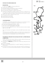
SHAPE OF THE FAN SPRAY

Vertical Fan Spray Pattern

SHAPE OF THE FAN SPRAY

Horizontal Fan Spray Pattern

- Air pressure too low
- Product viscosity too high
- Quantity of product too high

- Air pressure too high
- Product viscosity too low
- Quantity of product too low

- Regular jet

INSTRUCTIONS FOR USE AND RECOMMENDATIONS FOR A CORRECT APPLICATION 

Mix the paint product according to the technical data sheets of the products to be used. 
Filter the product before its use. 
Choose the size of the needle (

A

) / nozzle (

U

) / cap (

C

) kit depending on the product to be sprayed and the speed of 

desired job. For a precise indication of the spray gun set-up please refer to the main paint manufacturers’ specifications, by 
visiting the website www.walmec.com/solution finder, or simply scan the 

QR code below (*)

For Slim Kombat and Slim Xlight models, before using the spray gun, check if the removable diffuser (

D

) is properly installed. 

Tighten the nozzle (

U

) to the gun body (

K

) with a hand tightening torque device, set not less than 14 Nm. 

Verify that all the components are properly installed and tightened. 
Check the correct positioning of the cap (

C

) (vertical fan spray/horizontal fan spray): it must be “adequately locked” after 

the ring nut (

Cg

) has been tightened. 

“Fully open” product adjustment: pull the lever (

L

) completely back, and screw the needle-adjusting handwheel (

R

to the position where the lever begins to move. 
“Fully open” fan spray pattern adjustment: completely unscrew the jet adjusting handwheel (

G

). 

“Fully open” air flow adjustment: for models equipped with a flow rate adjuster (

P

), unscrew the flow-regulator handwheel 

completely (

P

). 

Fasten the color filter in its position, and fix/screw the cup to the spray gun’s product inlet (

E

), having previously filled it 

with the painting product to be used.  
Connect the spray gun to the compressed air supply (

I

). If possible, use an air pipe with a minimum section diameter equal 

to 10 mm (0.37”). 
If quick connect air couplings are required, use only high pressure/high flow elements: other coupling types do not allow 
an adequate and stable air flow for the proper use of the air gun. 
Make sure that the compressed air used is perfectly filtered from water, oil, and other impurities (for example with the 
installation of the Walcom FSRD3/4 filter unit, or the more efficient and complete TD

3

/TD

1

 PRO multifunctional filter and 

thermal conditioner unit). 
Pulling  back  the  lever  (

L

)  to  the  “1st  phase”  position,  that  is  without  releasing  the  paint  product,  adjust  the  air  supply 

pressure according to the most suitable pressure indications. If the spray gun works with less than ideal pressures, optimal 
finishes will not be obtained. 
Fine tune and adjust the shape of the fan spray, if necessary, by performing the following steps: 
- adjust the air pressure preferably by acting on the regulator/meter (

M

) and/or (

P

); 

- adjust the quantity of the product discharge, by acting on the needle-adjusting handwheel (

R

): turning it clockwise redu

-

ces the quantity of product dispensed; 
- adjust the fan spray by acting on the jet adjusting handwheel (

G

): turning it clockwise reduces the height of the fan spray 

area. 
To  paint,  pull  back  the  lever  (

L

)  completely  and  maneuver  the  spray  gun  so  that  the  jet  is  always  perpendicular  to  the 

surface to be painted, at the recommended painting distance for the model in use. 
It is always preferable to apply paint with horizontal movements and with the most uniform speed possible, overlapping at 
least 50% of each spray passage. Any displacements of the structure during the emission of the paint product can cause 
an uneven application of the paint layer. 
Always disconnect or close the air supply, limiting the pressure, when the spray gun is not used.

1 -


2 -


3 -


4 -


5 -


6 -


7 -


8 -


9 -


10 -


11 -


12 -


13 -


14 -


15 -


16 -


CORRECT APPLICATION

CORRECT SPRAY GUN SETUP 
BY MANUFACTURER - PAINT 
CHARTS  

Check the correct setup 
of the  spray gun here, 

or visit 

www.walmec.com/solution finder  

(*)

Summary of Contents for Walcom GENESI CARBONIO 360 LIGHT HTE BASE

Page 1: ...HTE Clear HVLP GEO GENESI TOP LINE HTE HVLP GEO SLIM KOMBAT HTE HTE SR HVLP SLIM XLIGHT SLIM XLIGHT HD HTE HTE SR HVLP SLIM SLIM HD HTE HTE SR HVLP EGO CARBONIO HTE HVLP EGO HTE HVLP AEROGRAFO SPRAYG...

Page 2: ...2...

Page 3: ...efahr Risque d incendie Peligro de incendio Perigo de inc ndio Pericolo ustioni Burn hazard Verbrennungsgefahr Risque de br lure Peligro de quemaduras Risco de queimadura Pericolo esplosione Explosion...

Page 4: ...comandazioni e istruzioni per l uso Conservare i presenti documenti assieme all aerografo RISCHI DI USO IMPROPRIO L aerografo deve essere utilizzato revisionato esclusivamente da personale qualificato...

Page 5: ...i diffusore rimovibile non soffiare aria compressa su passaggi interni dell aerografo ad esempio dall alimentazione aria se non stato precedentemente serrato l ugello pericolo proiezione diffusore CON...

Page 6: ...a compressa I Utilizzare possibilmente un tubo aria con sezione minima diametro 10 mm 0 37 Se sono necessari accoppiamenti con attacchi rapidi utilizzare solo quelli a flusso elevato gli altri tipi no...

Page 7: ...7 IT C U E G A R K I P L Cg M E G R K I P L Cg C M E E D...

Page 8: ...re avvitare con forza il coperchio 8 sulla tazza 7 assicurarsi che il tubo 9 sia inserito correttamente nei raccordi del regolatore 4 e del coperchio 8 Dopo aver collegato l aria compressa all entrata...

Page 9: ...tituire corpo valvola completo di astina 1 Lubrificare adeguatamente astina posteriore ed anteriore con olio minerale 2 Pulire ago e regolare in modo adeguato ll premistoppa minimo attrito 3 Sostituir...

Page 10: ...must be exclusively used overhauled by qualified and trained personnel Handling the spray gun is prohibited to persons whose ability to react is impaired by drugs alcohol medication or in any other w...

Page 11: ...user do not blow compressed air through internal spray gun passages for example from the air supply if the nozzle has not been previously tightened danger of diffuser projection SPECIAL CONDITIONS FOR...

Page 12: ...ble use an air pipe with a minimum section diameter equal to 10 mm 0 37 If quick connect air couplings are required use only high pressure high flow elements other coupling types do not allow an adequ...

Page 13: ...13 EN C U E G A R K I P L Cg M E G R K I P L Cg C M E E D...

Page 14: ...tightly screw the lid 8 onto the cup 7 make sure the hose 9 is correcting inserted in the regulator 4 and lid 8 fittings After connect compressed air to the air inlet 1 proceed as follows Slowly open...

Page 15: ...ont rod 1 Clean and lubricate front rod 2 Replace valve body including the rod 1 Properly lubricate the rear rod with mineral oil 2 Adjust the stuffing box properly minimum needle sliding friction 3 R...

Page 16: ...zusammen mit der Spritzpistole aufbewahren GEF HRDUNGEN DURCH NICHT BESTIMMUNGSGEM SSEN GEBRAUCH Die Spritzpistole darf ausschlie lich von qualifiziertem und geschultem Fachpersonal verwendet gewartet...

Page 17: ...t abnehmbarem Diffusor ausgestattet sind blasen Sie keine Druckluft auf interne Durchg nge der Spritzpistole z B von Luftzufuhr wenn die Luftd se zuvor nicht festgezogen wurde Gefahr Diffusor berstand...

Page 18: ...Mindestdurchmesser von 10 mm 0 37 verwenden Wenn Schnellanschl sse erforderlich sind d rfen nur Schnellanschl sse verwendet werden die f r hohe Durchs tze geeignet sind um einen angemessenen und stab...

Page 19: ...19 DE C U E G A R K I P L Cg M E G R K I P L Cg C M E E D...

Page 20: ...kel 8 auf der Bechermulde 7 kr ftig festschrauben Sicherstellen dass der Schlauch 9 korrekt an die Anschl sse des Reglers 4 und des Deckels 8 eingesetzt ist Nachdem die Druckluft an die Luftzufuhr 1 a...

Page 21: ...entilk rper komplett mit Stange auswechseln 1 Die vordere und hintere Stange mit Mineral l schmieren 2 Die Stopfbuchse reinigen und korrekt regulieren minimale Reibung beim Bewegen der Nadel 3 Die hin...

Page 22: ...aphe RISQUES D UTILISATION IMPROPRE Le pistolet peinture ne doit tre utilis entretenu que exclusivement par un personnel qualifi et entra n L utilisation du pistolet est interdite aux personnes dont l...

Page 23: ...mod les avec diffuseur amovible ne pas souffler d air comprim sur les parties internes de l a rographe par ex depuis l alimentation en air comprim si la buse n a pas t pr alablement serr e risque de...

Page 24: ...i des raccords rapides sont n cessaires n utilisez que des raccords haut d bit les autres types de raccords ne permet tent pas un d bit suffisant et stable Assurez vous que l air comprim utilis est pa...

Page 25: ...25 FR C U E G A R K I P L Cg M E G R K I P L Cg C M E E D...

Page 26: ...produit pulv riser visser avec force le bouchon 8 sur la cuvette 7 s assurer que le tuyau 9 soit branch correctement dans les raccords du r gleur 4 et du bouchon 8 Apr s avoir connect l air comprim l...

Page 27: ...gle aiguille 3 Lubrifier ad quatement les tiges post rieure et ant rieure avec huile min ral 4 Remplacer aiguille et buse 5 R gler ad quatement presse toupe pour minimum frottement au glissement de ai...

Page 28: ...e uso Conservar estos documentos junto con el aer grafo RIESGOS POR USO INADECUADO El aer grafo debe ser utilizado revisado exclusivamente por personal cualificado y preparado La manipulaci n del aer...

Page 29: ...sor desmontable no soplar aire comprimido sobre pasos interiores del aer grafo por ejemplo por la alimentaci n de aire si no se apret previamente la boquilla peligro de proyecci n del difusor CONDICIO...

Page 30: ...tar el aer grafo a la alimentaci n del aire comprimido I De ser posible utilizar un tubo de aire con una secci n m nima de di metro de 10 mm 0 37 Si se requieren acoples con conexiones r pidas utiliza...

Page 31: ...31 ES C U E G A R K I P L Cg M E G R K I P L Cg C M E E D...

Page 32: ...tapa 8 sobre la copa 7 comprobar que el tubo 9 est correctamente conectado en los racores del regu lador 4 y de la tapa 8 Despu s de conectar el aire comprimido en la entrada de aire 1 actuar de la si...

Page 33: ...la aguja 3 Lubricar de manera adecuada el asta trasera y delantera con aceite mineral 4 Sustituir aguja y boquilla 5 Ajustar de manera adecuada el prensaestopas fricci n m nima de deslizamiento de la...

Page 34: ...do Guarde estes documentos com o pistola de pintura RISCOS DE UTILIZA O INDEVIDA O aer grafo s deve ser utilizado revisado por pessoal qualificado e treinado O uso do aer grafo proibido a pessoas cuja...

Page 35: ...or remov vel n o usar ar comprimido nas passagens internas da pistola de pintura por exemplo do fornecimento de ar se o bico n o foi previamente apertado perigo de proje o do difusor CONDI ES ESPECIAI...

Page 36: ...do produto E Conectar o aer grafo alimenta o de ar comprimido I Se poss vel utilizar uma mangueira de ar com uma sec o m nima di metro 10 mm 0 37 Se forem necess rios engates r pidos utilizar apenas...

Page 37: ...37 PT C U E G A R K I P L Cg M E G R K I P L Cg C M E E D...

Page 38: ...o produto a ser pulverizado aperte bem a tampa 8 no copo 7 verifique se o tubo 9 est inserido corretamente nas conex es do regulador 4 e da tampa 8 Depois de ligar o ar comprimido entrada de ar 1 pro...

Page 39: ...ola e ou aparafusar o volante de ajuste da agulha 3 Lubrificar devidamente as varetas traseira e frontal com leo mineral 4 Substituir a agulha e o bico 5 Ajustar devidamente o bucim fric o deslizament...

Page 40: ...40 RUS 1 2 ATEX 0 85 A Walcom 90109 W...

Page 41: ...41 RUS pH 6 8 43 C UNI EN 1953 5 4 85 C...

Page 42: ...www walmec com solution finder QR Slim Kombat Slim Xlight D U K 14 C Cg L R G P P E I 10 0 37 Walcom FSRD3 4 Walcom TD3 TD1 PRO L M P R G L 50 1 2 3 4 5 6 7 8 9 10 11 12 13 14 15 16 www walmec com sol...

Page 43: ...43 RUS C U E G A R K I P L Cg M E G R K I P L Cg C M E E D...

Page 44: ...44 RUS HD 1 1 0 15 psi 1 2 17 psi HD HD HD HD 5 7 8 7 9 4 8 1 5 2 5 3 0 36 43 psi 5 8 1 2 3 4 5 6 7 8 9 1 2 3 4 1 1 2 3 4 5 6 9 8 7...

Page 45: ...45 RUS 1 2 3 4 5 1 2 3 4 5 1 2 1 2 1 2 3 4 5 1 2 3 4 5 1 2 3 1 90109 W 2 3 1 2 3 4 5 6 7 8 1 2 3 4 5 S Xlight S Kombat 6 7 8...

Page 46: ...Empfohlener Spr habstand Maximaler Druck Produktzufuhr MaximalerDruckDruckluftversorgung Druckluftverbrauch bei 2 bar 29 Psi Gr e Produktanschluss E Gr e Druckluftanschluss I Beh ltertyp Anmerkungen D...

Page 47: ...5 GENESI TOP LINE HVLP S 0 5 2 5 bar 7 36 psi 5 bar 73 psi G 1 4 M 100 150 mm 3 9 5 9 310 350l min 10 4 11 8 CFM S M 16x1 5 HVLP 2 bar 29 psi GENESI TOP LINE GEO S 0 5 2 5 bar 7 36 psi 5 bar 73 psi G...

Page 48: ...4 M SP 5 bar 73 psi G 1 4 M G 3 8 M HVLP 2 bar 29 psi SLIM XLIGHT HTE HD 1 5 3 bar 22 44 psi 5 bar 73 psi G 1 4 M HD MAX 1 bar 15 psi M 12x1 5 SLIM KOMBAT SLIM KOMBAT HTE S 0 5 2 5 bar 7 36 psi 5 bar...

Page 49: ...00 150 mm 3 9 5 9 280 l min 9 9 CFM I HVLP 2 bar 29 psi SLIM HTE SP 0 5 5 bar 7 73 psi 5 bar 73 psi G 1 4 M SP 5 bar 73 psi G 1 4 M G 3 8 M SLIM HVLP SP 0 5 5 bar 7 73 psi 5 bar 73 psi G 1 4 M SP 5 ba...

Page 50: ...entioned devices meet ATEX 2014 34 UE Directive and thus are suited for use in potentially explosive atmosphere Zones 1 and 2 within the limits of the classified zones and according to the Instruction...

Page 51: ...os HTE HVLP versiones S DECLARA que los aparatos antes mencionados responden a la Norma ATEX 2014 34 UE y por lo tanto son apropiados para el uso en atm sferas potencialmente explosivas Zona 1 y 2 den...

Page 52: ...lear HVLP GEO S GENESI TOP LINE HTE HVLP GEO S I SP SLIM KOMBAT HTE HVLP S I SP SLIM XLIGHT HTE HVLP S I SP HD SLIM HTE HVLP S I SP HD EGO CARBONIO HTE HVLP S EGO HTE HVLP S ATEX 2014 34 UE 1 2 2014 3...

Page 53: ...ht von Bearbeitungs Material oder Montagefehlern sonder von einer falschen Verwendung und Wartung abh ngen 2 Das Ausr stung durch Missgriff verletzt ver ndert oder durch nicht berechtigtes Personal be...

Page 54: ...serva o direito de recusar responsabilidade nos seguintes casos 1 Osdefeitosn os oresultadodefabricodefeituoso materiaisoumontagem mass odecorrentesdeusoincorretoemanuten oinadequada 2 O equipamento f...

Page 55: ...contrado Problema encontrado Timbro del rivenditore e data di vendita Dealer s stamp and date of sale Stempel del Wiederverk ufers und Verkaufsdatum Cachet du revendeur et date de la vente Sello del v...

Page 56: ...y www walmec com MADE IN ITALY WALMEC S p A DIREZIONE HEADQUARTERS Via Trieste 10 31025 S Lucia di Piave TV Italy Tel 39 0438 6611 Fax 39 0438 661333 e mail walmec walmec com Web www walmec com WALMEC...

Reviews: