background image

5

Warning: Suspended loads

• 

When carrying out any work in the vicinity of the fan, wear protective equipment, see 2.2 Personal protective 

equipment,

• 

Never step under a suspended load.

• 

Ensure that no one is under a suspended load.

Delivery

Each fan leaves our factory in perfect electrical and mechanical condition. It is recommended that the fan is transported to 

the installation site in its original packaging.

Check delivery

• 

Check the packaging for transport damage. Any damage must be noted in the cargo manifest.

• 

Check that the delivery is complete.

Unpacking

Warning

When removing the transport packaging, there is a risk of damage from sharp edges, nails, staples, splinters, etc.
• 

Unpack the fan carefully.

• 

Check the fan for obvious transport damage.

• 

Do not remove the packaging until shortly before installation.

• 

Wear protective equipment for any work in the vicinity of the fan, see 2.2 Personal protective equipment

Transport

Safety instructions

• 

The fan must never be carried by the connection cable, terminal box, impeller, guard grille, inlet connection or 

silencer.

• 

In the case of open transport, ensure that no water can penetrate the motor or other sensitive components.

• 

It is recommended that the fan be transported to the installation site in its original packaging. 

Caution: Careless loading or unloading may cause damage to the fan.

• 

Carry out loading or unloading carefully.

• 

Use lifting equipment designed for the load.

• 

Observe the transport arrows on the packaging.

• 

The packaging is only used as transport protection and must not be used for lifting. 

Storage

• 

Store the fan in the original packaging in a dry, dust-free place protected from the weather.

• 

Avoid exposure to extreme heat or cold.

Important

Danger from loss of function of the motor bearing
• 

Avoid excessively long storage periods (recommendation: max. 1 year).

• 

Before installation, check that the motor bearing is functioning correctly.

5.  Description

5.1.  GB, GBG and GBV with EC motor

The fans are driven by EC motors. The fans must be controlled with a potentiometer (0-10V). All motors are suitable for 

50/60 Hz. The input voltage for single-phase units is in the range 200V and 277V, for three-phase units the input voltage is 

380 and 480V.

The maximum fluid temperature is +120°C.

Note

When installing EC motors, ensure that RCDs of type class: B or B+ are present in the circuit.

Summary of Contents for GB

Page 1: ...Airbox type GB GB HT GBV GBG Assembly and operating instructions Version 7 0 B04...

Page 2: ...8 7 Accessories 8 8 Installation 9 8 1 Mounting positions 10 8 2 In the W Connect system CL 12 9 CL 10 10 min 380 Pa CL 9 9 min 295Pa CL 7 7 W connect 10 8 3 Changing the discharge direction only GBV...

Page 3: ...he system relevant conditions and requirements of the system manufacturer or system builder Safety devices must not be dismantled bypassed or rendered inoperative The fan may only be used in perfect c...

Page 4: ...rotective equipment Protective equipment must be worn when carrying out any work in the vicinity of the fan Protective clothing Safety shoes Protective gloves Hard hat Safety glasses Hearing protectio...

Page 5: ...n the case of open transport ensure that no water can penetrate the motor or other sensitive components It is recommended that the fan be transported to the installation site in its original packaging...

Page 6: ...ENTRY AIR ENTRY Table 2 Dimensions Airbox GB Dimen sions mm A B C D E F G H I J K L M N O P GB 180 470 412 272 224 134 105 218 483 470 95 244 43 366 180 470 320 GB 225 522 455 301 256 147 121 251 635...

Page 7: ...in mm GBV 355 GBV 400 GBV 450 GBV 500 GBV 560 GBV A 500 670 670 670 800 800 B 500 670 670 670 800 800 C 420 590 590 590 720 720 D 378 548 548 548 676 678 E 355 404 454 504 xml ph 630Nipple dimension...

Page 8: ...blowing via contact protection grille is also possible The fan is suitable for conveying clean air The maximum permissible operating data on the type plate apply to an air density of 1 2 kg m NN and a...

Page 9: ...connectors from our accessories see chapter Accessories Prerequisites Make sure that the fan and all its components are undamaged Make sure that the information on the type plate fan and motor corres...

Page 10: ...ke sure that the drain socket is always at the lowest point of the fan so that the condensation water can drain off 8 2 In the W Connect system CL 12 9 CL 10 10 min 380 Pa CL 9 9 min 295Pa CL 7 7 W co...

Page 11: ...3 Changing the airflow direction 8 4 Assembly disassembly of impeller internal rotor motor Important Damage to the motor and the impeller The ball bearings of the motor and the balanced impeller can b...

Page 12: ...exagon socket screw 6 Impeller 7 Steel hub 8 Aluminium hub The hub is not used for the fan Hub is shown without impeller for clarity Table of tightening torques for various bushing types Socket type 1...

Page 13: ...box revision switch evenly Connect the cable end in a dry environment Install a disconnecting device permanently all pole contact opening min 3 mm in the electrical installation Protective earth cond...

Page 14: ...d by the customer in the application Never exceed the maximum impeller speed specified on the type plate of the fan Caution Damage due to non use of a sine filter Walpol always recommends an all pole...

Page 15: ...2 1 Safety instructions Troubleshooting maintenance repair may only be carried out by appropriately qualified persons for details see Table 1 Qualification The 5 safety rules must be observed see 2 3...

Page 16: ...cked Contact Walpol Fan does not reach nominal speed Defective motor winding Contact Walpol Drive motor misaligned Contact Walpol Control devices if used such as frequency converter or transformer are...

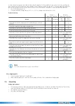
Page 17: ...X X Check that the fan and its components are used as intended X see normal operating conditions Check the current consumption and compare this with the rated data X X Check the vibration dampers if...

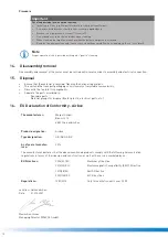
Page 18: ...the national regulations The unit and the transport packaging consist mainly of recyclable raw materials Dismantle the fan into its components Separate the parts according to Reusable parts Material g...

Page 19: ...1 2010 Safety of machinery Electrical equipment of machines Part 1 General requirements DIN EN 61000 6 1 2007 Electromagnetic compatibility EMC Part 6 1 Generic standards Immunity for residential comm...

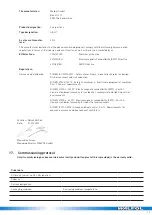
Page 20: ...onnected to mains without control Via contactor control 0 10 V signal EC motor Transformer Frequency converter Sine Filter Shielded cables Sealing of connection cable FESTER Clamp fit of wires Motor p...

Page 21: ...minutes For single phase fans enter in line Current L1 A pressure between suction and discharge side of the fan If a volume flow measurement is not possible the value can be calculated using the follo...

Page 22: ...in kitchen technology Observe cleaning according to VDI 2052 The intervals may be shortened in case of heavy soiling Please note If cleaning maintenance intervals are not observed warranty and guaran...

Page 23: ...23 Visual inspec tion Cleaning Maintenance Note Specialist company Stamp Date Signature...

Page 24: ...ww eu...

Reviews: