All fault codes can be reset manually by switching Off/On the CS (cabin switch)
.
Fault codes
F0-F7 and U0-U7 are reset automatically if the function in question is running (function verifi ed).
Fault codes L and H are reset automatically if the battery voltage becomes correct. Fault code E
is reset automatically if the control system has not received any signal from the relevant control
device for 6 minutes.
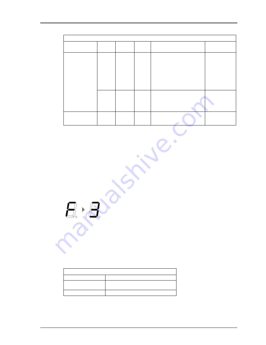
Example of sequence of fault codes:
Output No. 3 short-circuited.
Control devices
If a control device button is held down for too long, the control device is blocked and cannot be used
for a number of minutes. Fault code E fl ashes on the display. The fault is also indicated on a non-
active coil control device with a lock button, if this is connected to Ctrl 4. The LED on the coil control
device then fl ashes the same number of times as the number on the control device in question, see
the list in section "11.2.2 Fault codes" on page 8.
Example:
Control device 2 is blocked, the LED on the coil control device then fl ashes twice, goes
out for a moment, fl ashes twice again, etc.
Coil control device’s LED
Fixed light
The coil control device is active
Extinguished (weak glim-
mer)
The coil control device is not active
Flashing
One of the other control devices is blocked
Fault codes
Identifi cation
Code 1
Code 2
Code
3
Information
Other
F
Output short-circuit-
ed/high current
0-9
Which output has short-circuited/
has high current. Fault code is
reset automatically if the function
in question is running (function
verifi ed).
1-7 U 0 - U 7 , d i s -
played only af-
ter the respec-
t i v e o u t p u t /
function has
been active.
8
Control power
9
Sensor power
Output not connect-
ed/cable breakdown
0-7
Which output is not connected/
has cable breakdown. Fault
code is reset automatically if the
function in question is running
(function verifi ed).
Displayed only af-
ter the respective
output U0-U7 has
been active.
A
Internal fault
0-
Contact support
if the lift does not
function.
Chapter 4 Liftgate Installation
page 30
Summary of Contents for BZ-33
Page 17: ...Chapter 4 Liftgate Installation Electric and Hydraulic Diagram G page 17...
Page 18: ...Chapter 4 Liftgate Installation Electric and Hydraulic Diagram with Auto tilt G page 18...
Page 61: ...Add silicone caulk to seal gaps between tracks and vehicle body page 61...


