Summary of Contents for HYDRA Series
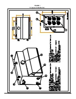
Page 11: ...FIGURE 3 Identification des composantes 11...
Page 12: ...FIGURE 4 Sch ma type d une installation une zone 12...
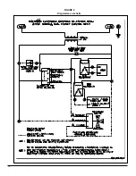
Page 13: ...FIGURE 5 Diagramme lectrique 13...
Page 14: ...FIGURE 6 Diagramme en chelle 14...
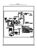
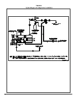
Page 15: ...FIGURE 7 Sch ma type d une installation Bi nergie sans valve 3 voies 15...
Page 16: ...FIGURE 8 Sch ma type d une installation Bi nergie avec valve 3 voies 16...
Page 17: ...17 COMPOSANTES ET PI CES DE REMPLACEMENT...
Page 18: ...LISTE DE PI CES HYDRA B50080 Rev B 18...
Page 30: ...FIGURE 3 Component Identification 11...
Page 31: ...FIGURE 4 Typical Diagram of a Single Zone Installation 12...
Page 32: ...FIGURE 5 Electrical Diagram 13...
Page 33: ...FIGURE 6 Ladder Diagram 14...
Page 34: ...FIGURE 7 Typical Diagram of a Dual Energy Installation without 3 way Valve 15...
Page 35: ...FIGURE 8 Typical Diagram of a Dual Energy Installation with 3 way Valve 16...
Page 36: ...17 COMPONENTS AND REPLACEMENT PARTS...

