SECTION 1
INSTALLATION
1.1) SAFETY
LABELING AND WARNING SIGNS
The words
DANGER, WARNING
and
CAUTION
are used to
identify the levels of seriousness of certain hazards. It is
important that you understand their meaning. You will notice
these words in the manual as follows :
DANGER
Immediate hazards that
WILL
result in death, serious
bodily injury and/or property damage.
WARNING
Hazards or unsafe practices that CAN result in
death, bodily injury and/or property damage.
CAUTION
Hazards or unsafe practices that
CAN
result in bodily
injury and/or property damage.
1.2) IMPORTANT
INFORMATION
WARNING
Non-observance of the safety regulations outlined
in this manual will potentially lead to consequences
resulting in death, serious bodily injury and/or
property damage.
a) It is the homeowner’s responsibility to engage a
qualified technician for the installation and
subsequent servicing of this boiler;
b) Do not store gasoline or any other flammable
substances, such as paper, carton, etc. near the
boiler;
c) Ask the technician installing your boiler to show and
explain to you the main disconnect switch or circuit
breaker;
d) Before calling for service, be sure to have the
information page (p. 8) of your manual close by in
order to be able to provide the contractor with the
required information, such as the model and serial
numbers of the boiler.
WARNING
Installation and repairs performed by unqualified
persons can result in hazards to them and to
others. Installations must conform to local codes
or, in the absence of same, to codes of the country
having jurisdiction.
The information contained in this manual is
intended for use by a qualified technician, familiar
with safety procedures and who is equipped with
the proper tools and test instruments.
Failure to carefully read and follow all instructions
in this manual can result in death, bodily injury
and/or property damage.
1.3)
DANGER OF FREEZING
CAUTION
If your boiler is shut down during the cold weather
season, water pipes may freeze, burst and cause
serious water damage. Turn off the water supply and
bleed the pipes.
If the heater is left unattended during the cold weather
season, take the following precautions:
a) Close the main water valve in the house and purge the
pipes if possible. Open all the faucets in the house;
b) Ask someone to frequently check the house during the
cold weather season to make sure that there is sufficient
heat to prevent the pipes from freezing. Tell this person
to call an emergency number if required.
1.4)
HEATING WITH HOT WATER
Your HYDRA electric boiler was carefully assembled and
checked in our plant, so that it will deliver warmth and
comfort to your home for many years to come.
This manual is intended to provide the necessary information
for the installation of the unit, how it functions, and explain
security measures which are particular to this type of
equipment.
It is essential that the persons installing, operating or
adjusting the boiler carefully read this manual, in order to
completely understand and be familiar with the procedures
to be followed.
Any questions relative to the operation, maintenance or
guarantee should be directed to the company where the
equipment was purchased.
Upon completion of the installation, this manual should be
placed back into its original envelope and kept near the
boiler for future reference.
3
Summary of Contents for HYDRA Series
Page 11: ...FIGURE 3 Identification des composantes 11...
Page 12: ...FIGURE 4 Sch ma type d une installation une zone 12...
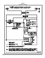
Page 13: ...FIGURE 5 Diagramme lectrique 13...
Page 14: ...FIGURE 6 Diagramme en chelle 14...
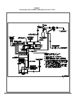
Page 15: ...FIGURE 7 Sch ma type d une installation Bi nergie sans valve 3 voies 15...
Page 16: ...FIGURE 8 Sch ma type d une installation Bi nergie avec valve 3 voies 16...
Page 17: ...17 COMPOSANTES ET PI CES DE REMPLACEMENT...
Page 18: ...LISTE DE PI CES HYDRA B50080 Rev B 18...
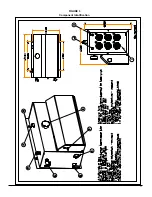
Page 30: ...FIGURE 3 Component Identification 11...
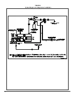
Page 31: ...FIGURE 4 Typical Diagram of a Single Zone Installation 12...
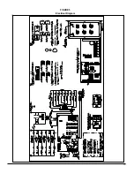
Page 32: ...FIGURE 5 Electrical Diagram 13...
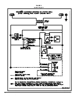
Page 33: ...FIGURE 6 Ladder Diagram 14...
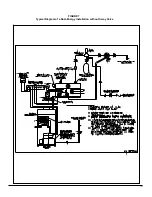
Page 34: ...FIGURE 7 Typical Diagram of a Dual Energy Installation without 3 way Valve 15...
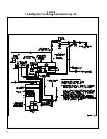
Page 35: ...FIGURE 8 Typical Diagram of a Dual Energy Installation with 3 way Valve 16...
Page 36: ...17 COMPONENTS AND REPLACEMENT PARTS...


