6.
The flow of water through the system must be sufficient
to continuously discharge the energy generated by the
boiler. If not, the High Limit protector will disconnect all
the electric elements and a more or less frequent
cycling mode will be established by the Safety Control
(see the Technical Specifications Table, p. 10);
7.
In order to ensure satisfactory water flow, the friction in
the piping system must not exceed the capacity of the
circulator;
8.
After having completed all piping connections, run water
through the system and purge the air. The automatic
vent should be in operation.
Note: Remove the panel on the right side of the unit and
check to see if the elements and the temperature sensor are
watertight.
1.9)
ELECTRIC POWER SUPPLY
WARNING
Risk of fire.
The conductor sizing must conform to the last
edition of the local or national codes.
Failure to follow this rule can result in death,
bodily injury and/or property damage.
All electrical wiring must conform to the standards and
regulations in force and the Canadian Electrical Code CSA
C22.1.
Electrical power to the boiler must come from a 120/240V 60
Hz, single phase, 3-wire, grounded circuit, protected by an
appropriately sized breaker, based on the total rating of the
boiler. Refer to the boiler nameplate and the technical
specifications in this manual, p. 10, to select the proper
breaker and determine the wire size.
Power supply to the unit can be made using copper or
aluminum wires. The wire size must be decided in
accordance to unit power consumption, the over current
protection type and capacity, the wire type and length, and
the environment where the unit is installed. If an aluminum
wire is used, other precautions (such as the use of a DE-OX
inhibitor) must be taken to insure the conformity of the
installation. In all cases, all the factors affecting the wire
gauge must be considered and the installation codes
followed.
The exterior of the unit must have an uninterrupted ground to
minimize the risk of bodily harm. A ground terminal is
supplied with the control box for that purpose.
In the event that wires inside the unit require replacement,
these must be as same type as originals. (Copper wiring
only).
1.9.1) Connecting the circulating pump
The electronic circuit is designed in such a way that the
circulator functions based on demand by the thermostat, or if
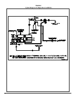
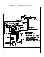
a high limit condition is detected. Refer to Figure 4, page 12
for the connecting of the circulating pump.
1.9.2) Connecting
the
thermostat
Single heating zone
Connect the low voltage thermostat to W1 and R terminals
located inside the control panel on the electronic board, as
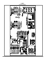
represented on Figure 5, p. 13.
Multiple heating zones
Connect the contacts of the motorized valves or pump
controls to W1 and R terminals inside the control panel on
the electronic board.
The anticipator inside the thermostat must be adjusted
according to the electrical load connected to the thermostat.
1.9.3) Thermostat heat anticipator adjustment (if
required)
Certain thermostats are equipped with a heat anticipator that
must be adjusted according to the instructions supplied.
This is to ensure that the heating mode is comfortable and
economical.
Generally speaking, on a single stage thermostat, a reading
of the current must be taken with an ammeter as follows:
1) Move the anticipator to its highest setting, rendering
it ineffective.
2) Remove the wire from the “W1” terminal and
connect an ammeter between the terminal and the
wire.
3) Call for heat by raising the set point on the
thermostat and allow the boiler to run for 3 to 4
minutes to reach its peak output.
4) Once the current has stabilized, a reading should
be taken and the anticipator adjusted to that value.
If longer heating cycles are desired, the anticipator
can be set to a higher value
1.9.4) Connecting the outdoor sensor
Mount the sensor on an outside wall, protected from direct
sunlight, so that it will accurately measure the outside
temperature. Install 2 only #20 wires between the outdoor
sensor and the terminals identified as S1 and S2 on the
electronic board terminal.
5
Summary of Contents for HYDRA Series
Page 11: ...FIGURE 3 Identification des composantes 11...
Page 12: ...FIGURE 4 Sch ma type d une installation une zone 12...
Page 13: ...FIGURE 5 Diagramme lectrique 13...
Page 14: ...FIGURE 6 Diagramme en chelle 14...
Page 15: ...FIGURE 7 Sch ma type d une installation Bi nergie sans valve 3 voies 15...
Page 16: ...FIGURE 8 Sch ma type d une installation Bi nergie avec valve 3 voies 16...
Page 17: ...17 COMPOSANTES ET PI CES DE REMPLACEMENT...
Page 18: ...LISTE DE PI CES HYDRA B50080 Rev B 18...
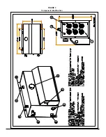
Page 30: ...FIGURE 3 Component Identification 11...
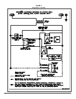
Page 31: ...FIGURE 4 Typical Diagram of a Single Zone Installation 12...
Page 32: ...FIGURE 5 Electrical Diagram 13...
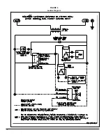
Page 33: ...FIGURE 6 Ladder Diagram 14...
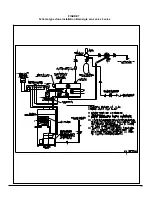
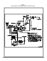
Page 34: ...FIGURE 7 Typical Diagram of a Dual Energy Installation without 3 way Valve 15...
Page 35: ...FIGURE 8 Typical Diagram of a Dual Energy Installation with 3 way Valve 16...
Page 36: ...17 COMPONENTS AND REPLACEMENT PARTS...

