background image


SECTION 2 

OPERATION 


2.1) 

ADJUSTMENTS AND START-UP 


CAUTION 

The boiler must be filled with water and all air purged 
from the system, before turning on the power. 


If the power is turned on before the boiler is filled with 
water, the elements will become seriously damaged. 


1. 

With the help of a small screwdriver, adjust the boiler 
temperature screw on the board potentiometer located 
on the control board, to between "90°F - 120°F - 150°F - 
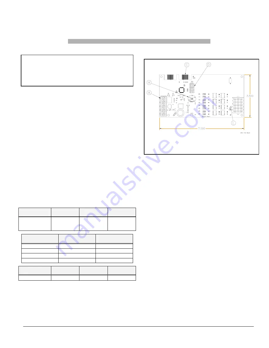
180°F - 210°F" (see Figure 1, item B); 

2. 

In the event that the modulating capacity feature of 
the boiler is desired,

 an outdoor sensor will need to be 

installed and wired onto the Hydra electronic board 
(terminals S1 and S2). Once the outdoor sensor is wired 
to the board, the boiler capacity will modulate if the 
outdoor air temperature is between -10

˚

C (14

˚

F) and 

10

˚

C (50

˚

F) (see figure 2, p. 9 for more details on 

modulation).  If capacity modulation of the boiler is not 
required for the application, do not proceed with the 
installation of the outdoor sensor and leave the 
terminals S1 and S2 unwired. 

3. 

Check if the dip switches "NUMBER OF ELEMENTS" 
are in the proper position. Refer to Table 2 and Figure 1, 
item D to determine the position of the dip switch, based 
on the power rating; 

4. 

Turn on the power; 

5. 

Adjust room thermostat according to the required 
temperature. 


TABLE 2 

DIP SWITCHES POSITION 


Dip switch 1 

Dip switch 2 

Dip switch 3 

New Hydra with 

immersed 

sensor 

OFF ON  ON 


Number of 

elements 

Dip switch 4 

Dip switch 5 

3 OFF 

OFF 

4 OFF ON 
5 ON 

OFF 

6 ON ON 


Dip switch 6 

Dip switch 7 

Dip switch 8 

Not used 

OFF 

OFF 

OFF 


FIGURE 1 

HYDRA ELECTRONIC BOARD 


A: BOARD TERMINAL STRIP 
B: POTENTIOMETER 
C: TROUBLESHOOTING PORT 
D: DIP SWITCHES FOR BOARD CONFIGURATION 
E: FUSE 2A (AUTO-RESET) 


2.2) CHECKING 

THE 

CONTROLS 


Operational Controls 

After having made sure that the boiler is completely filled 
with water and that there is no call for heat, turn on the 
power to the unit. 


For this verification, disconnect the outdoor sensor from the 
S1 and S2 terminals of the Hydra electronic board. As a 
result, all the elements will remain functional, regardless of 
the outside temperature; 


Set the thermostat in the house to 30°C (85°F). The 
circulator should start-up and the elements should start 
sequentially, one by one (randomly), at approximately 15 
second intervals. Pilot lights located on the control board 
provide a visual check of the operation of the boiler; 


The circulator stays on for as long as there is a call for heat; 


By observing the temperature indicator, allow the water 
temperature to rise to 60°C (140°F). Then, turn the electronic 
Limit Control counter clockwise to 32°C (90°F). The 
elements will stop sequentially, one by one, at 1 second 
intervals between each. Now, the water temperature must be 
adjusted with the "90°F - 120°F - 150°F - 180°F - 210°F" set 
screw on the electronic board. 


Once the verification is completed, reconnect the outdoor 
sensor to S1 and S2 of the Hydra electronic board (if 
required). 

Summary of Contents for HYDRA Series

Page 1: ...401M D HYDRA24 E2401M D HYDRA29 E2401M D 2009 08 25 X40156 Rev B Fabriqu par Corporation UTC Canada Division ICP 3400 boulevard Industriel Sherbrooke Qu bec Canada J1L 1V8 C INSTALLATEUR TECHNICIEN UT...

Page 2: ...4 INFORMATION p 8 TABLEAUX ET FIGURES TABLEAU 1 D GAGEMENT MINIMUM p 4 TABLEAU 2 POSITION DES INTERRUPTEURS DIP p 6 TABLEAU 3 SP CIFICATIONS TECHNIQUES p 10 FIGURE 1 CARTE LECTRONIQUE HYDRA p 6 FIGURE...

Page 3: ...ou dans le cas d absence de codes locaux elle doit tre conforme aux codes nationaux qui s appliquent Les renseignements contenus dans ce manuel s adressent un technicien qualifi exp riment dans ce typ...

Page 4: ...90 210 F Protection contre le gel lorsque requise MISE EN GARDE Seule une solution base de propyl ne glycol peut tre utilis e dans ce syst me de chauffage l eau afin de pr venir le gel Il est recomman...

Page 5: ...mpue pour minimiser les risques de blessures corporelles si jamais un probl me lectrique se produisait Un connecteur de mise la terre est inclus dans la bo te de contr le pour effectuer cette connexio...

Page 6: ...g e OFF ON ON Nombre d l ments Interrupteur 4 Interrupteur 5 3 OFF OFF 4 OFF ON 5 ON OFF 6 ON ON Interrupteur 6 Interrupteur 7 Interrupteur 8 Non utilis OFF OFF OFF FIGURE 1 CARTE LECTRONIQUE HYDRA A...

Page 7: ...e b timent est ligible ce tarif d lectricit et pour conna tre la fa on de faire pour l obtenir Les contr les de transfert Bi nergie BCEH sont sp cialement con us pour r pondre aux normes des fournisse...

Page 8: ...pus s accumuler au fond de la chaudi re et recouvrir les l ments chauffants Proc dure 1 Laisser refroidir la chaudi re 2 Fermer les valves d entretien qui sont install s la sortie et l entr e de la c...

Page 9: ...HIQUES 1 ET 2 Ajustement du potentiom tre Tpot 210 F Selon le graphique 1 la temp rature de l eau variera entre 210 F Tmax eau et 170 F Tmin eau Si la temp rature ext rieure est plus grande ou gale 10...

Page 10: ...ation Amp 38 62 75 83 100 120 Amp rage du circuit dimensionnement du conducteur 1 48 78 94 104 125 150 Disjoncteur fusible maximum recommand Amp 1 50 80 100 125 125 150 Alimentation Retour D bit d eau...

Page 11: ...FIGURE 3 Identification des composantes 11...

Page 12: ...FIGURE 4 Sch ma type d une installation une zone 12...

Page 13: ...FIGURE 5 Diagramme lectrique 13...

Page 14: ...FIGURE 6 Diagramme en chelle 14...

Page 15: ...FIGURE 7 Sch ma type d une installation Bi nergie sans valve 3 voies 15...

Page 16: ...FIGURE 8 Sch ma type d une installation Bi nergie avec valve 3 voies 16...

Page 17: ...17 COMPOSANTES ET PI CES DE REMPLACEMENT...

Page 18: ...LISTE DE PI CES HYDRA B50080 Rev B 18...

Page 19: ...10 L MENT EAU 240V 5KW 14 L99H012 L MENT EAU 240V 3KW 15 L99H011 L MENT EAU 240V 4KW 16 A20015 SONDE EXT RIEUR 12 C 17 B20179 01 ASSEMBLAGE SOUTIEN ARRI RE 18 B02293 24 ISOLATION 19 L02G001 PORTE FUSI...

Page 20: ...RA20 E2401M D HYDRA24 E2401M D HYDRA29 E2401M D 2009 08 25 X40156 Rev B Manufactured by UTC Canada Corporation ICP Division 3400 Industrial Boulevard Sherbrooke Quebec Canada J1L 1V8 C INSTALLER SERVI...

Page 21: ...8 4 INFORMATION p 8 TABLES AND FIGURES TABLE 1 MINIMUM CLEARANCE p 4 TABLE 2 DIP SWITCHES POSITION p 6 TABLE 3 TECHNICAL SPECIFICATIONS p 10 FIGURE 1 HYDRA ELECTRONIC BOARD p 6 FIGURE 2 BOILER WATER...

Page 22: ...information contained in this manual is intended for use by a qualified technician familiar with safety procedures and who is equipped with the proper tools and test instruments Failure to carefully r...

Page 23: ...col may be used in this hydronic heating system to prevent freezing It is recommended to add a maximum of 50 of propylene glycol mixture to ensure proper operation Do not use automotive anti freeze et...

Page 24: ...e an uninterrupted ground to minimize the risk of bodily harm A ground terminal is supplied with the control box for that purpose In the event that wires inside the unit require replacement these must...

Page 25: ...h 3 New Hydra with immersed sensor OFF ON ON Number of elements Dip switch 4 Dip switch 5 3 OFF OFF 4 OFF ON 5 ON OFF 6 ON ON Dip switch 6 Dip switch 7 Dip switch 8 Not used OFF OFF OFF FIGURE 1 HYDRA...

Page 26: ...l heater Contact your Hydro office to find out if your property is eligible to receive this rate and how to go about obtaining it BCEH dual energy controls are specially designed to Hydro standards Th...

Page 27: ...at the bottom of the boiler and covered the heating elements Procedure 1 Let the boiler cool down 2 Close the maintenance valves which are installed at the water inlet and outlet of the boiler N B It...

Page 28: ...outdoor temperature is lower or equal to 10 C 14 F Graph 2 indicates that the boiler will maintain a water temperature of 210 F Water temperature Tmax water If outdoor temperature is between 10 C 14...

Page 29: ...N A N A N A 4 4 Consumption Amp 38 62 75 83 100 120 Minimum circuit ampacity wire sizing 1 48 78 94 104 125 150 Maximum recommended circuit breaker fuse Amp 1 50 80 100 125 125 150 Supply Return Minim...

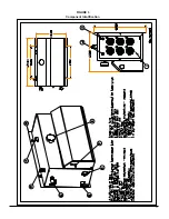
Page 30: ...FIGURE 3 Component Identification 11...

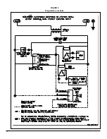
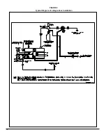
Page 31: ...FIGURE 4 Typical Diagram of a Single Zone Installation 12...

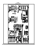
Page 32: ...FIGURE 5 Electrical Diagram 13...

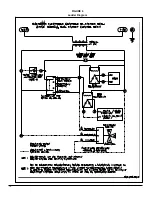
Page 33: ...FIGURE 6 Ladder Diagram 14...

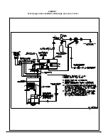
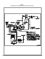
Page 34: ...FIGURE 7 Typical Diagram of a Dual Energy Installation without 3 way Valve 15...

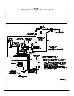
Page 35: ...FIGURE 8 Typical Diagram of a Dual Energy Installation with 3 way Valve 16...

Page 36: ...17 COMPONENTS AND REPLACEMENT PARTS...

Page 37: ...PARTS LIST HYDRA B50080 Rev B 18...

Page 38: ...R PROBE 13 L99H010 WATER ELEMENT 240V 5KW 14 L99H012 WATER ELEMENT 240V 3KW 15 L99H011 WATER ELEMENT 240V 4KW 16 A20015 OUTDOOR SENSOR 12 C 17 B20179 01 MOUNTING PLATE ASSEMBLY 18 B02293 24 INSULATION...

Reviews: