Mechanical High Limit Control
Use the same procedure as outlined in the preceding
paragraph, but now on the mechanical aquastat, located at
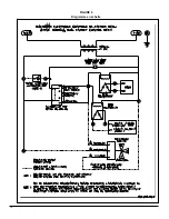
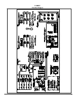
the center left of the control panel (see Figure 5. p. 13, note
3). This time the elements will all disengage at the same
time. The mechanical limit aquastat must be set 20°F above
the temperature on the electronic board.
Modulation Control
If an outdoor sensor has been installed as specified on page
5, section 1.9.4, the overall capacity of your boiler will be
reduced upon an increase of the outdoor air temperature as
shown on Figure 2, p. 9. The purpose of this feature is to
considerably reduce the number of heating cycles.
2.3)
BCEH DUAL-ENERGY INSTALLATION
In order to obtain a special rate (DT rate) from your hydro-
electric power supplier on residential applications, your
HYDRA boiler can be hooked-up to an existing oil heater.
Contact your Hydro office to find out if your property is
eligible to receive this rate and how to go about obtaining it.
BCEH dual-energy controls are specially designed to Hydro
standards. The BCEH control selects the least expensive
energy source, either oil or electricity, based on outside
temperature or a signal from Hydro.
The BCEH dual-energy control will start-up the oil burner
when the contact in the outdoor dual-energy sensor closes
(due to a drop in temperature or other signal), even if the
thermostat in the house is not calling for heat. It will stop
when the temperature in the boiler reaches its target on the
Limit Control. Only in such a case is an anti-gravity valve
(flow check valve) or are motorized zone valves required.
A three-way motorized valve will direct the water flow either
to the oil fired heater or to your electric HYDRA boiler,
depending on the signal received from the outdoor dual-
energy sensor.
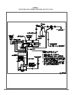
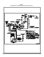
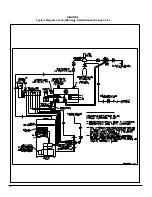
To install boiler, refer to Figures 6, 7 and 8 on pages 14, 15
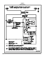
and 16 and remove jumper as shown on Figure 5, p. 13,
note 4.
7
Summary of Contents for HYDRA Series
Page 11: ...FIGURE 3 Identification des composantes 11...
Page 12: ...FIGURE 4 Sch ma type d une installation une zone 12...
Page 13: ...FIGURE 5 Diagramme lectrique 13...
Page 14: ...FIGURE 6 Diagramme en chelle 14...
Page 15: ...FIGURE 7 Sch ma type d une installation Bi nergie sans valve 3 voies 15...
Page 16: ...FIGURE 8 Sch ma type d une installation Bi nergie avec valve 3 voies 16...
Page 17: ...17 COMPOSANTES ET PI CES DE REMPLACEMENT...
Page 18: ...LISTE DE PI CES HYDRA B50080 Rev B 18...
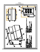
Page 30: ...FIGURE 3 Component Identification 11...
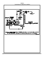
Page 31: ...FIGURE 4 Typical Diagram of a Single Zone Installation 12...
Page 32: ...FIGURE 5 Electrical Diagram 13...
Page 33: ...FIGURE 6 Ladder Diagram 14...
Page 34: ...FIGURE 7 Typical Diagram of a Dual Energy Installation without 3 way Valve 15...
Page 35: ...FIGURE 8 Typical Diagram of a Dual Energy Installation with 3 way Valve 16...
Page 36: ...17 COMPONENTS AND REPLACEMENT PARTS...


