Boiler water temperature variation according to outdoor temperature
GRAPH 2
GRAPH 1
Range of water temperature variation according to
potentiometer adjustment
Water temperature variation according to outdoor temperature
FIGURE 2
9
APPLICATION EXAMPLE FOR GRAPHS 1 AND 2
Potentiometer adjustment (Tpot) = 210˚F
Based on graph 1, the water temperature will vary between 210˚F (Tmax water) and 170˚F (Tmin water)
•If outdoor temperature is greater or equal to 10˚C (50˚F):
Graph 2 indicates that the boiler will maintain a water temperature of 170˚F (Water temperature = Tmin
water)
•If outdoor temperature is lower or equal to -10˚C (14˚F):
Graph 2 indicates that the boiler will maintain a water temperature of 210˚F (Water temperature = Tmax
water)
•If outdoor temperature is between -10˚C (14˚F) and 10˚C (50˚F):
Graph 2 indicates that the boiler will maintain a water temperature between 210˚F and 170˚F. At 0˚C
(32˚F), the water temperature will be mid-way between Tmax water and Tmin water. Therefore, we can
expect a water temperature of approximately 190˚F.
70
90
110
130
150
170
190
210
90
110
130
150
170
190
210
Ajustement potentiomètre (
o
F)
Potentiometer setpoint (
o
F)
Te
m
p
é
ra
tur
e
de
l
'e
a
u (
o
F)
Wat
e
r t
e
m
p
er
a
tu
re (
o
F)
Tmax eau
Tmax water
Tmin eau
Tmin water
-15
-10
-5
0
5
10
15
Te mpérature e xtérie ure (
o
C)
Outdoor air te mp (
o
C)
Tmax e au
Tmax wate r
Tmin eau
Tmin water
Summary of Contents for HYDRA Series
Page 11: ...FIGURE 3 Identification des composantes 11...
Page 12: ...FIGURE 4 Sch ma type d une installation une zone 12...
Page 13: ...FIGURE 5 Diagramme lectrique 13...
Page 14: ...FIGURE 6 Diagramme en chelle 14...
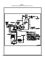
Page 15: ...FIGURE 7 Sch ma type d une installation Bi nergie sans valve 3 voies 15...
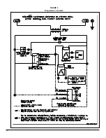
Page 16: ...FIGURE 8 Sch ma type d une installation Bi nergie avec valve 3 voies 16...
Page 17: ...17 COMPOSANTES ET PI CES DE REMPLACEMENT...
Page 18: ...LISTE DE PI CES HYDRA B50080 Rev B 18...
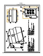
Page 30: ...FIGURE 3 Component Identification 11...
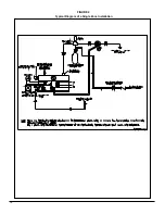
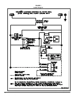
Page 31: ...FIGURE 4 Typical Diagram of a Single Zone Installation 12...
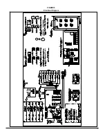
Page 32: ...FIGURE 5 Electrical Diagram 13...
Page 33: ...FIGURE 6 Ladder Diagram 14...
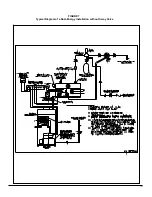
Page 34: ...FIGURE 7 Typical Diagram of a Dual Energy Installation without 3 way Valve 15...
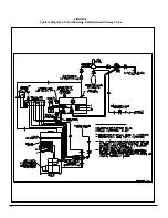
Page 35: ...FIGURE 8 Typical Diagram of a Dual Energy Installation with 3 way Valve 16...
Page 36: ...17 COMPONENTS AND REPLACEMENT PARTS...

