TABLE 3
HYDRA – TECHNICAL SPECIFICATIONS
10
Power (Kw)
9
15
18
20
24
29
Net capacity (BTU/h)
30 708
51 180
61 416
68 240
81 888
98 948
Volts - Hertz - Phase
Electrical element #1 (Kw)
3
5
5
5
4
5
Electrical element #2 (Kw)
3
5
5
5
4
5
Electrical element #3 (Kw)
3
5
5
5
4
5
Electrical element #4 (Kw)
N/A
N/A
3
5
4
5
Electrical element #5 (Kw)
N/A
N/A
N/A
N/A
4
5
Electrical element #6 (Kw)
N/A
N/A
N/A
N/A
4
4
Consumption (Amp)
38
62
75
83
100
120
Minimum circuit ampacity (wire sizing)
1
48
78
94
104
125
150
Maximum recommended circuit breaker / fuse (Amp)
1
50
80
100
125
125
150
Supply - Return
Minimum water flow USG/min (L/min.)
3.25 (12.3)
5.15 (19.5)
6.44 (24.4)
6.84 (25.9)
8.2 (31.0)
9.9 (37.6)
24 VAC output ("C-24 VAC" terminals)
Overall dimensions (width x depth x height)
Shipping weight
1
Always refer to applicable local and national codes.
RATING AND PERFORMANCE
ELECTRICAL SYSTEM
GENERAL INFORMATION
1" NPT male - 1" NPT female
20 VA
25.5" x 12.5" x 16.5"
50 kg / 110 lbs
120 / 240 - 60 - 1
Summary of Contents for HYDRA Series
Page 11: ...FIGURE 3 Identification des composantes 11...
Page 12: ...FIGURE 4 Sch ma type d une installation une zone 12...
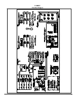
Page 13: ...FIGURE 5 Diagramme lectrique 13...
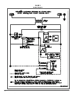
Page 14: ...FIGURE 6 Diagramme en chelle 14...
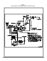
Page 15: ...FIGURE 7 Sch ma type d une installation Bi nergie sans valve 3 voies 15...
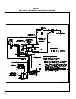
Page 16: ...FIGURE 8 Sch ma type d une installation Bi nergie avec valve 3 voies 16...
Page 17: ...17 COMPOSANTES ET PI CES DE REMPLACEMENT...
Page 18: ...LISTE DE PI CES HYDRA B50080 Rev B 18...
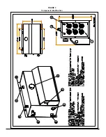
Page 30: ...FIGURE 3 Component Identification 11...
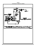
Page 31: ...FIGURE 4 Typical Diagram of a Single Zone Installation 12...
Page 32: ...FIGURE 5 Electrical Diagram 13...
Page 33: ...FIGURE 6 Ladder Diagram 14...
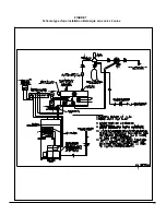
Page 34: ...FIGURE 7 Typical Diagram of a Dual Energy Installation without 3 way Valve 15...
Page 35: ...FIGURE 8 Typical Diagram of a Dual Energy Installation with 3 way Valve 16...
Page 36: ...17 COMPONENTS AND REPLACEMENT PARTS...

