


30
31
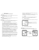
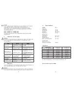
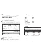
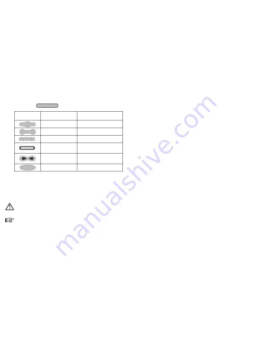
Correction of Spray Pattern Imperfections
The following table shows how to correct a defective spray pattern.
Spray pattern
test
Fault
Required adjustment
Spray pattern is split in
the centre
• setting a wider spray pattern
Spray pattern is too thick
at the ends
• Setting a more rounded spray
pattern
The spray pattern shows
rather large droplets
•
In
crease the nozzle air pres-
sure
Material application in the
centre of the spray pattern
is very thin
• Decrease the nozzle air pres-
sure
Spray pattern is split in
the centre
• Increase the nozzle diameter
• Reduce nozzle air pressure
• Increase material pressure
Spray pattern is very
spherical
• Reduce material pressure
• Increase nozzle air pressure
5.5
Retooling of Spray Gun
Combinations of air cap, material control nozzle and needle, designed to match
specific spraying media tpyes and grades, form a unit - namely the nozzle insert
assembly. In order maintain the desired spray-finish quality standard always replace
the complete nozzle insert assembly.
Warning
Prior to retooling: Make sure that the spray gun is in unpressurized condition, i.e. all
air and material inputs must be shut off - if not, imminent risk of injury.
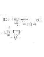
Note
In order to perform the following procedures please use the drawing at the begin-
ning of these operating instructions.
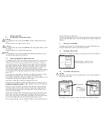
Replacement of Air Cap
1. Unscrew the knurled air cap nut in (pos. 1) from the front part.
2. Pull the air cap in (pos. 2) of the gun front.
3. Position the required air cap on the front.
4. Screw the air cap nut in (pos. 1) onto the front.
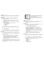
Desired spray pattern
Replacement of Material Nozzle and Needle
1. Remove the air cap (see
5.5 Replacement of Air Cap
).
2. Unscrew the material nozzle (pos. 3) from the gun body (pos. 6). Remove the
sealing washer (pos.4) and the air distribution ring in (pos. 5).
3. Unscrew the drawbar (pos. 24).
4. Unscrew the cap (pos. 23) and the threaded bushing (pos. 22) from the gun
body.
5. Pull off the material control needle with the Parts (pos. 17-20) from the gun
body.
Installation of the new nozzle insert assembly and the remaining parts is performed
in the reverse order.
6
Cleaning
6.1
Safety Warnings
•
Prior to any servicing and repair work: Make sure that the spray gun is in
unpressurized condition, i.e. all air and material inputs must be shut off - if not,
imminent risk of injury.
•
No open fires, naked light and smoking allowed in the work area. When
spraying readily flammable media such as cleaning solutions, there is an
increased risk of fire and explosion.
•
Observe the safety warnings issued by the manufacturer. Aggressive and cor-
rosive media represents risks and hazards to personal health.
6.2
Cleaning - Complete
Regular cleaning and lubrication of the spray gun has to be performed, in order to
increase the service life and the function of the spray gun.
Clean the gun only with cleaning solutions recommended by the manufacturer of
the spraying material used at the time. It is important to make sure that cleaning
solutions do not contain any of the following constituents:
•
halogenated hydrocarbons (e.g. 1,1,1-trichloroethane, methylene chloride,
etc.)
•
acids and acidiferous cleaning solutions
•
regenerated solvents (so-called cleaning dilutions)
•
paint removers.
The above constituents cause chemical reactions with the electroplated compon-
ents resulting in corrosion damage.
WALTHER Spritz-und Lackiersysteme is not responsible for any damages resulting
from such treatment.
Clean the spray gun
•
prior to each change of the spraying medium
•
at least once a week
•
as often as may be required by the spraying medium handled and the resultant
degree of fouling.
Summary of Contents for PILOT WA 450
Page 3: ...4 5 PILOT WA 450...


