background image

36

37

Cleaning and Maintenance

6.1 

Safety Instructions

• 

Prior to any servicing and repair work: Make sure that the spray gun is in 

unpressurised condition, i.e. all air and material inputs must be shut off - if not, 

imminent Risk of Injury .

• 

No open fires and naked lights as well as smoking are allowed in the work 

area. This is a major requirement to prevent the euer present risk of fire and 

explosion, particularly when spraying readily flammable media such as, for 

example cleaning solutions, etc.

• 

It is important that all processing specifications and safety warnings issued by 

the manufacturer of cleaning media are duly complied with. Remember: 

Aggressive and corrosive media represents risks and hazards to personal 

health.

6.2 

Cleaning - Complete

The spray gun should be frequently cleaned and lubricated so as to ensure a long 

service life and functional reliability. Cleaning of the gun only with cleaning solutions 

recommended by the manufacturer of the spraying material used at the time. It is 

im-portant to make sure that cleaning solutions do not contain any of the following 

constituents:

• 

halogenated hydrocarbons (e.g. 1,1,1-trichloroethane; methylene chloride, etc.)

• 

acids and acidiferous cleaning solutions

• 

regenerated solvents (so-called cleaning dilutions)

• 

paint removers

The above constituents cause chemical reactions with electroplated components 

resulting in corrosion damage.

WALTHER Spritz- und Lackiersysteme is not liable for any damages resulting from 

improper treatement of the gun.

Clean the spray gun

• 

prior to each change of the spraying medium.

• 

at least once a week.

• 

as often as may be required by the spraying medium handled and the resultant 

degree of fouling.

Caution

Never immerse the spray gun in solvent or any other cleaning solution as such 

measure is highly likely to affect the functional reliability and efficiency of the gun.

Caution

Do not use any hard, pointed or sharp-edged objects when cleaning the spray gun. 

Any damage of the precision-made parts are likely to affect your spraying results.

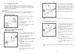
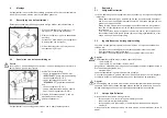
1.  Dismantle the spray gun (see 

5.5 Retooling the Spray Gun

).

2.  Use a soft brush together with a compatible cleaning solution to clean the air 

cap and nozzle.

3.  Use a suitable cloth with a compatible cleaning solution to clean the gun body 

and all remaining parts.

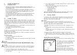
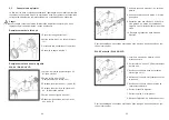
4.  Apply a thin film of the appropriate grease type/grade to the:

• 

sealing collar of the piston

• 

O-ring of the piston

• 

material control needle

• 

needle spring

• 

inside of the gun body

Make sure to use a non-acidic, non-resinogenic grease type/ grade and apply 

same with a soft brush. Assemble the spray gun in reverse order.

6.3 

Cleaning - Routine

The spray gun need not necessarily be dismantled for cleaning if and when the 

spraying medium is changed in regular intervals or upon termination of work 

(depending, of course, an the material used).

Notice

lt is recommended practice to clean and lubricate the spray gun frequently in 

accordance with Chapter 

6.2 Cleaning - Complete

, as this will greatly help towards 

ensuring a Jong service life and functional reliability.

The following requirements must be met before the routine cleaning work can be 

performed:

• 

the material tank must be clean and then filled with a compatible cleaning 

solution.

• 

cleaning solution should neuer be sprayed - yet the material pressure must be 

available at the gun.

The spraying system must be in Operation if a spray gun is to be cleaned.

1.  Take the spray gun into Operation (see 

5.2 Starting / Stopping Requirements

).

2.  Do not stop the spray gun until clear cleaning solution emerges from the nozz-

le.

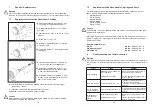
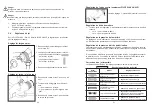
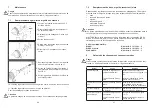
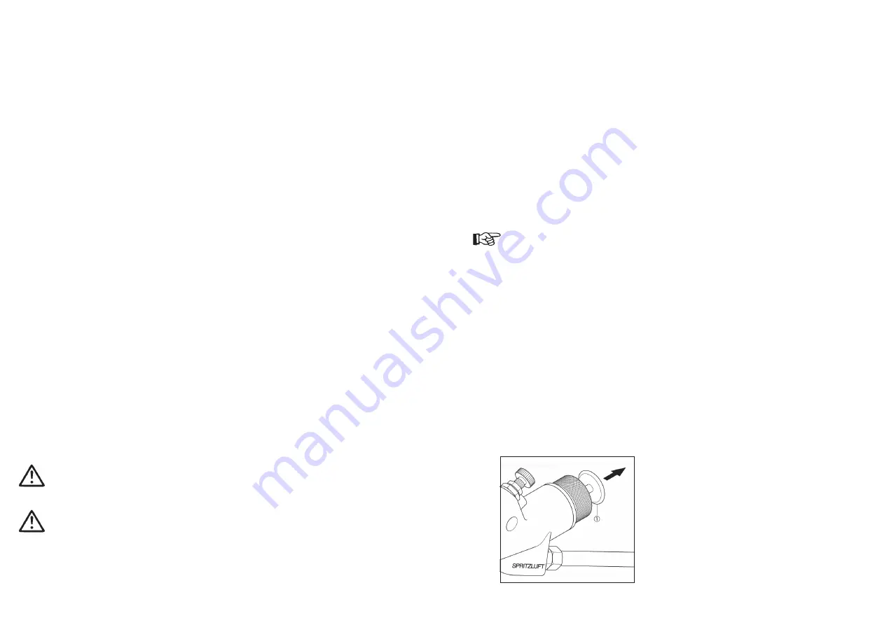
Only WA XV needle-pull /  WA XV-HVLP

The material Input can be released by hand so that the complete spraying system 

must not be taken into operation.

1. Pull the disk 

 at the end of the spray gun back. 

The material inlet is now open and both the 

material duct and the material needle will be 

washed clean.

2. Do not let go of the disk 

 until clear cleaning 

solution emerges from the nozzle.

All pressures should now be removed from the 

complete spraying system - which should be left in 

this condition until it is taken into operation again.

Summary of Contents for V 20 664

Page 1: ...iebsanleitung Operating Instructions Instructions de Service Gebruiksaanwijzing Automatische Spritzpistolen Automatic Spray Guns Pistolets de Pulv risation Automatiques Automatische Spuitpistolen PILO...

Page 2: ...ursets Maintenance kits Kits de r paration Reparatiesets V 16 115 03 3 WA XV V 16 116 03 3 WA XV ziehbar needle pull tirette met trekker V 16 117 03 3 WA XV HVLP 45 PILOT WA XV HVLP PILOT WA XV Stand...

Page 3: ...Seite 6 22 Page 24 40 Page 42 58 Site 60 76 Pagina 78 94...

Page 4: ...al Besondere Hinweise Das Produkt ist zum Einbau in ein anderes Ger t bestimmt Die Inbetriebnahme ist so lange untersagt bis die Konformit t des Endproduktes mit der Richtlinie 2006 42 EG festgestellt...

Page 5: ...2 09 000 O Ring 24 V 20 660 31 000 Steuerkolben 25 V 20 651 06 000 Manschette 26 V 20 660 34 000 St tzscheibe 27 wahlweise Materialnadel V 20 660 51 3 28 V 10 506 02 000 Nadelmutter 29 V 20 651 07 000...

Page 6: ...leitung mit dem Spritzmaterial versorgt werden Die Spritzpistole kann an Materialdruckgef e und Pumpensysteme angeschlossen werden 3 Sicherheitshinweise 3 1 Kennzeichnung der Sicherheitshinweise Warnu...

Page 7: ...le Materialien verspritzen Umherschwebende Partikel gef hrden Ihre Gesundheit Tragen Sie im Arbeitsbereich der Spritzpistole einen Geh rschutz Der erzeug te Schallpegel der Spritzpistole von ca 86 dB...

Page 8: ...aube dient zur Regulierung der Mittenluft Materialdurchflussmenge einstellen 1 Drehen Sie die Regelschraube der Materialzufuhr aus der Grundstellung Kerbe an der Federbuchse in Richtung um den Materia...

Page 9: ...ab 5 Ziehen Sie die beiden Federstifte her aus 6 Schrauben Sie die Federbuchse mit einem Schraubenschl ssel SW 27 ab Die Montage der neuen D seneinlage sowie der restlichen Bauteile erfolgt in umge ke...

Page 10: ...pritzergebnis verschlechtern 1 Zerlegen Sie die Spritzpistole s 5 5 Spritzpistole umr sten 2 Reinigen Sie den Luftkopf und die Materiald se mit einem Pinsel und dem Reinigungsmittel 3 Reinigen Sie all...

Page 11: ...rlegen Sie die Spritzpistole gem Abschnitt 5 5 Materiald se und nadel wech seln wenn die folgenden Bauteile ausgetauscht werden m ssen Materiald se Druckfeder des Kolbens Materialnadel Nadelfeder Mans...

Page 12: ...erst uberluft G 1 4 Steuerluft G 1 4 Materialzufuhr G 3 8 Druckbereiche Steuerluftdruck max 8 bar Materialdruck max 10 bar WA XV max 15 bar WA XV ziehbar WA XV HVLP Zerst uberluftdruck siehe Tabelle m...

Page 13: ...be rendered invalid if any changes are made to the equipment wit hout prior consultation with us Manufacturer WALTHER Spritz und Lackiersysteme GmbH K rntner Str 18 30 D 42327 Wuppertal Tel 49 0 202 7...

Page 14: ...ing Collar 21 V 09 102 11 000 O Ring 22 V 20 660 33 000 Screw Plug 23 V 09 102 09 000 O Ring 24 V 20 660 31 000 Control Piston 25 V 20 651 06 000 Sealing Collar 26 V 20 660 34 000 Backup Washer 27 opt...

Page 15: ...onnected to material pressure tanks pumping and circula tion systems 3 Safety Instructions 3 1 Safety Warning Symbols Warning This pictograph and the accompanying warning note Warning indicates possib...

Page 16: ...th hazard Make sure to wear suitable Kearing protectors Remember Spray guns pro duce sound levels of up to about 86 dB A which are highly likely to cause hearing defects Make sure your working area is...

Page 17: ...ecrease of flow rate direction increase of flow rate Adjustment of the Material Pressure This adjustment can only be made at the controls of the pumping or circulation system or material pressure tank...

Page 18: ...ont attachment use a Size 12 mm wrench 4 Unscrew the material Input regulating screw 5 Pull the two spring pins off 6 Unscrew the spring retaining bush use a Size 27 mm wrench 7 Remove the compression...

Page 19: ...un Any damage of the precision made parts are likely to affect your spraying results 1 Dismantle the spray gun see 5 5 Retooling the Spray Gun 2 Use a soft brush together with a compatible cleaning so...

Page 20: ...ay gun in accor dance with 5 5 Replacement of Material Nozzle and Needle Material Nozzle Piston Spring Material Needle Needle Spring Piston Sealing Collar Piston O Ring Caution Parts marked must be lu...

Page 21: ...Specification Data Weight 920 g Connections Atomizing Air G 1 4 Control Air G 1 4 Material Inlet G 3 8 Pressure Ranges Control Air Pressure max 8 bar Material Pressure max 10 bar WA XV max 15 bar WA...

Page 22: ...tre part ou utilisation inad quate de l appareil annulent la validit de cette d claration Fabricant WALTHER Spritz und Lackiersysteme GmbH K rntner Str 18 30 D 42327 Wuppertal Tel 49 0 202 787 0 Fax 4...

Page 23: ...Manchette 21 V 09 102 11 000 Joint torique 22 V 20 660 33 000 Vis d obturation 23 V 09 102 09 000 Joint torique 24 V 20 660 31 000 Piston de commande 25 V 20 651 06 000 Manchette 26 V 20 660 34 000 R...

Page 24: ...irculation Plusieurs unit s peuvent ainsi tre approvisionn es simultan ment par le tuyau circulating dispos en cercle Le pistolet peut tre raccord des r servoirs sous pression ou des pompes 3 Consigne...

Page 25: ...la sant Portez une protection contre le bruit dans la zone de travail Le niveau sonore de 86 dB A peut entra ner des troubles auditifs Aucune source d tincelles ne doit exister dans le secteur de tra...

Page 26: ...alimentation mati re encoche sur la douille ressort vers pour r duire le d bit vers pour augmenter le d bit R gulation de la pression de la mati re Ce r glage ne peut s effectuer qu partir de la pompe...

Page 27: ...de pr cision de l alimentation mati re 5 Sortez les deux tiges ressort 6 D sserrez la douille de ressort avec une cl de 27 Pour I assemblage d un nouveau syst me de buse ainsi que des autres pi ces p...

Page 28: ...raient tre endommag es et affecter vos r sultats d application 1 D sassemblez le pistolet voir 7 2 Remplacement de buse et d aiguille 2 Nettoyez la t te et la buse avec un pinceau enduit de l agent ne...

Page 29: ...ressort d aiguille manchette du piston rondelle du piston Attention Les pi ces signal es par une doivent tre lubrifi es avant leur installation dans le corps du pistolet avec une graisse neutre non ac...

Page 30: ...d Air de pulv risation G 1 4 Air de commande G 1 4 Alimentation mati re G 3 8 Pression Pression de commande max 8 bar Pression de mati re max 10 bar WA XV max 15 bar WA XV tirette WA XV HVLP Pression...

Page 31: ...sproken wijziging aan het hierna beschreven product of bij oneigenlijk gebruik verliest deze verklaring haar geldigheid Fabrikant WALTHER Spritz und Lackiersysteme GmbH K rntner Str 18 30 D 42327 Wupp...

Page 32: ...0 Afsluitschroef 23 V 09 102 09 000 O ring 24 V 20 660 31 000 Stuurzuiger 25 V 20 651 06 000 Manchet 26 V 20 660 34 000 Steunschijf 27 naar keuze Materiaalnaald V 20 660 51 3 28 V 10 506 02 000 Naaldm...

Page 33: ...hillende spuitpistolen via de ringvormig ge nstalleerde rondpompleiding gelijktijdig worden voorzien van spuitmateriaal Het spuitpistool kan worden aangesloten aan materiaaldrukvaten en pompinstallati...

Page 34: ...id Draag bij het werken met het spuitpistool een oorbescherming Het geluidsni veau van het spuitpistool bereikt ca 86 db A en kan schade aan het gehoor veroorzaken Vuur open licht en roken is verboden...

Page 35: ...cht Instelling van het debiet 1 Draai de regelschroef van de materiaaltoevoer uit de basispositie inkeping aan de veerbus in de richting om het debiet te verminderen in de richting om het debiet te ve...

Page 36: ...oolvoorzetstuk SW 12 4 Schroef de materiaalnozzle op het pistoolvoorzetstuk SW 12 5 Trek de beide veerstiften eruit 6 Schroef de veerbus met een schroefs leutel SW 27 Ios Het monteren van het nieuwe n...

Page 37: ...te onderdelen kunnen beschadigen en het spuitresultaat verslechte ren 1 Haal het spuitpistool uit elkaar zie 5 5 Ombouwen van het spuitpistool 2 Reinig de luchtkop en de materiaalnozzle met een kwast...

Page 38: ...ald vervan gen als de volgende onderdelen moeten vervangen worden materiaalnozzle drukveer van de zuiger materiaalnaald naaldveer afdichtingsring van de zuiger O ring van de zuiger Opgelet De met aang...

Page 39: ...gegevens Gewicht 920 g Aansluiting Verstuivingslucht G 1 4 Besturingslucht G 1 4 Materiaaltoevoer G 3 8 Drukbereik Besturingsluchtdruk max 8 bar Materiaaldruk max 10 bar WA XV max 15 bar WA XV met tr...

Page 40: ...on noi o in caso di uso impro prio la presente dichiarazione cessa di essere valida Costruttore WALTHER Spritz und Lackiersysteme GmbH K rntner Str 18 30 D 42327 Wuppertal Tel 49 0 202 787 0 Fax 49 0...

Page 41: ...ta 21 V 09 102 11 000 Guarnizione circolare 22 V 20 660 33 000 Tappo a vite 23 V 09 102 09 000 Guarnizione circolare 24 V 20 660 31 000 Pistone di comando 25 V 20 651 06 000 Bussola di tenuta 26 V 20...

Page 42: ...lazione ad anello La pistola a spruzzo pu essere collegata a serbatoi materiale a pressione e sistemi di pompaggio e di circola zione 3 Norme di sicurezza 3 1 Pittogrammi per le norme di sicurezza Avv...

Page 43: ...la salute Indossare sempre cuffie antirumore nella zona di lavoro della pistola a spruzzo La pressione sonora della pistola a spruzzo di ca 86 dB A e pu provocare un danni all udito Non provocare scin...

Page 44: ...tata materiale 1 Girare la vite di regolazione dell alimentazione materiale dalla posizione di base tacca sulla boccola per molla in direzione per diminuire la portata materiale in direzione per aumen...

Page 45: ...la apertura chiave 12 4 Svitare la vite di regolazione per la por tata del materiale 5 Estrarre le due spine per la molla 6 Svitare la boccola per la molla con una chiave per dadi apertura chiave 27 I...

Page 46: ...e 1 Scomporre nei particolari la pistola a spruzzo v 5 5 Riattrezzare la pistola a spruzzo 2 Pulire il cappello aria e l ugello materiale con un pennello e detergente 3 Pulire tutti gli altri componen...

Page 47: ...ello ed ago materiale quando devono essere sostituiti i seguenti componenti ugello materiale molla di compressione del pistone ago materiale molla ago bussola di tenuta del pistone guarnizione circola...

Page 48: ...Alimentazione materiale G 3 8 Range di pressione Pressione aria compressa max 8 bar Pressione materiale max 10 bar WA XV max 15 bar WA XV estraibile WA XV HVLP Pressione aria nebulizzazione vedere tab...

Page 49: ...ss Ger te und Fl ssigkeitspumpen Materialumlaufsysteme Kombinierte Spritz und Trockenboxen Absaugsysteme mit Trockenabscheidung Absaugsysteme mit Nassabscheidung Trockner Zuluft Systeme Atemschutzsyst...

Reviews: