


33
32
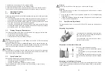
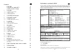
The models PILOT WA 715-U / WA 735-HVLP-U / WA 755-HVLP
PLUS
-U /WA 718-U-K
and WA 738-HVLP-U-K with connection for paint circulation can be integrated into a
system with circulation.
The models PILOT WA 725-HVLP / WA 735 HVLP-U / WA 728 HVLP-K and
WA 738 HVLP-U-K are pure low-pressure spray guns working with a spraying air
pressure of 0.7 bar at an intake air pressure of 4.5 bar.
With the models PILOT WA 745-HVLP
PLUS
and WA 755 HVLP
PLUS
-U the intake air pres-
sure ranges from 3.0 to 3.3 bar for a spraying air pressure from 1.2 to 1.4 bar.
3
Safety Warnings
3.1
Safety Warning Symbols
Warning
This pictograph and the accompanying warning note
„Warning“
indicate possible
risks and dangers for yourself. - Possible consequences: Injuries of any kind.
Caution
This pictograph and the accompanying warning note
„Caution“
indicate possible
damage to equipment. - Possible consequences: Damage to equipment, workpi-
eces, etc.
Notice
This pictograph and the accompanying note
„Notice“
indicate additional and useful
information to help you handling the spray gun with even greater confidence and
efficiency.
3.2
Generally Applicable Safety Precautions
►
All applicable accident prevention rules and regulations as well as other recog-
nised industrial safety and health rules and regulations must be observed at all
times.
►
Use the spray gun only in well-ventilated rooms. Fire, naked flames and smoking
are strictly prohibited within the working area. WARNING – during the spraying
of flammable materials (e.g. lacquers, adhesives, cleaning agents, etc.), there is
an increased risk to health as well as an increased risk of explosion and fire.
►
You must ensure that the spray gun is properly earthed (grounded) either sepa-
rately or in connection with the equipment with which it is being used
(max. resistance 10
6
Ω).
►
Before carrying out maintenance or servicing work, always ensure that the air
and material feed to the spray gun have been de-pressurised. Risk of injury!
►
When spraying materials, do not place your hands or other parts of the body
infront of the pressurised nozzle or the spray gun. - Risk of injury!
►
Never point the spray gun at persons or animals. - Risk of injury!
►
Always observe the spraying and safety instructions given by the manufacturers
of the spraying material and the cleaning agent. Aggressive and corrosive mate-
rials in particular can be harmful to health.
►
Always wear hearing protection when using the gun or when in the vicinity of a
gun that is in use. The noise level generated by the spray gun is approx.
86 dB(A).
►
Exhaust air containing particles (overspray) must be kept away from the working
area and personnel. In spite of these measures, always wear the regulation
breathing masks and protective overalls when using the gun. Airborne particles
represent a serious health hazard!
►
After carrying out assembly or maintenance work, always ensure that all nuts,
bolts and screw connections have been fully tightened before the gun is used.
►
Use only original replacement parts, since WALTHER can only guarantee safe
and fault-free operation for original parts.
►
For further information on the safe use of the spray gun and the spraying mate-
rials, please contact WALTHER Spritz- und Lackiersysteme GmbH,
D-42327 Wuppertal, Germany.
4
Assembly / Installation
This spray gun is delivered in completely assembled condition. Before taking the
spray gun into operation perform the following preparations:
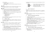
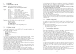
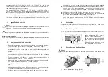
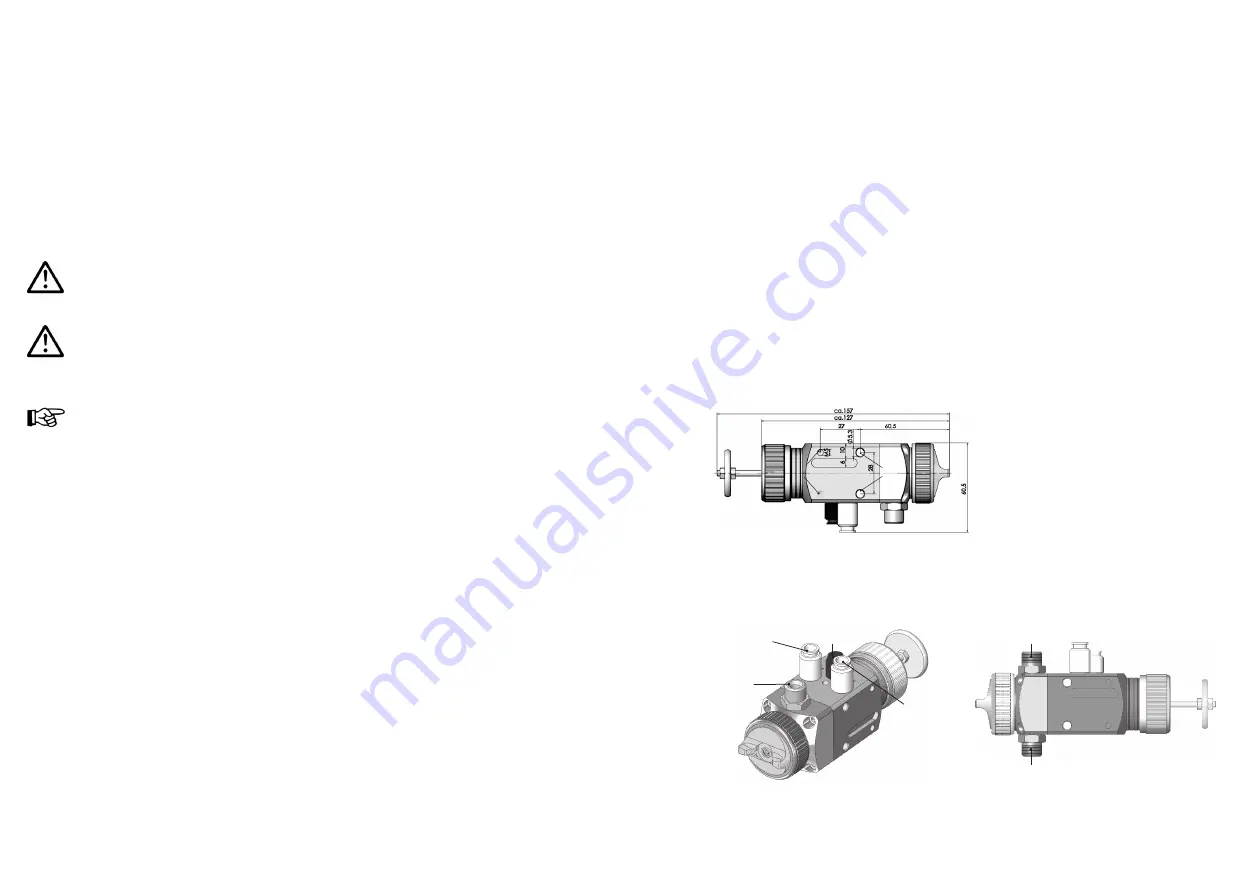
4.1
Mounting of Spray Gun
Install the gun in a suitable and stable mounting device as shown in the following
example:
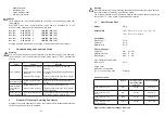
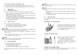
4.2
Connection of Input Lines
Warning
Make sure not to confuse the control and atomizing air connections -risk of injury.
1 = Material inlet fitting (G 1/4“)
2 = Control air inlet fitting (G 1/8“) marked with
ST
Use the two through holes here with a
dia. of 5.3 mm (1) with a hole spacing
of 28 mm and the two threaded holes
M5 with a hole spacing of 28 mm (2).
Other mounting devices upon request.
(2)
(1)
5
5
3
2
1
4


