


Rev. 1.5
Operating Manual Table-top Greasing Device TBV-H-0x-xx
Page 11 of 35
Walther Systemtechnik GmbH
–
D 76726 Germersheim
Telefon: +49 (0)7274-7022-0 Telefax: +49 (0)7274-7022-91
http://www.walther-2000.de
–
info@walther-2000.de
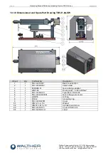
5 Initial Start-up
5.1 Mounting and Installation
IMPORTANT
We recommend adding a maintenance unit to the control air.
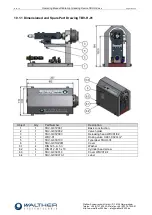
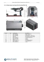
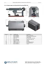
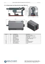
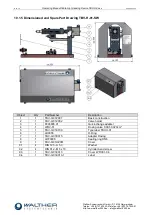
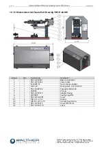
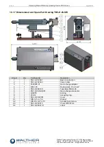
Figure TBV-02 without protective cover
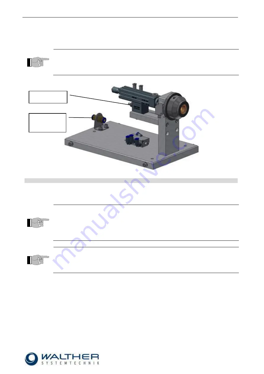
5.2 Adjusting the Machine
NOTE
In order to ensure optimal operation of the valves, make sure that the air supply pressure is
set to approx. 6 bar.
The lubricant feed pressure should not exceed 200 bar at the input. To ensure this, check the
pressure conversion ratio of the lubricant feed pump. The feed pressure may be reduced by
means of an air pressure control valve (The use of an air pressure control valve may be
advantageous, although it is not imperative).
IMPORTANT
All dosing valves are tested by the manufacturer prior to shipping. Due to testing, residues of
test liquid may be found inside the valve.
1) Make sure that the lubricant feed hose is filled with lubricant and all air is removed. Then connect
feed hose and air connectors according to drawing.
2) For first operation, set valve to maximum dosage (i.e. turn adjustment screw to outmost position).
3) If the adjustment screw cannot be turned, change position of change-over-valve. The adjustment
screw should now be unlocked.
4) Execute a first shot of lubricant. Then set the adjustment screw to the desired grease quantity.
5) The minimum cycle time depends on the viscosity of the lubricant, as well as on the lubricant feed
pressure
.
6) The tabletop greasing unit can be fastened to the work station with 3 screws M6
(bore holes in the
base plate).
Connection
Compressed air
6 bar
Connection
Material


