12
English
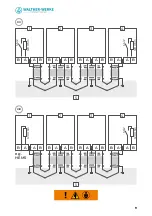
load management system to the next Wallbox.
Please note:
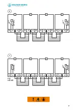
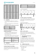
• Two conductors per bus line are used.
• Connect the bus using two separate bus lines each
between the Wallboxes (Line in and Line out).
• Connect only one bus line each to the first
(Line out) and last (Line in) devices.
Item
Designation
1
First Wallbox or external load manage-
ment on the bus
2
Second Wallbox on the bus
3
Wallbox X on the bus
4
Last Wallbox on the bus
2.3
Bus system with central wiring
in distributor
Central wiring
differs as follows:
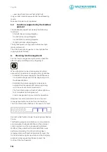
• Four conductors per bus line are used.
• Only two conductors each are needed on the first
and last devices.
• Connect the screens of the individual bus lines in
the central distributor.
are explained below
Item
Designation
1
First Wallbox or external load manage-
ment on the bus
2
Second Wallbox on the bus
3
Wallbox X on the bus
4
Last Wallbox on the bus
5
Central distributor
3. Local and external load management
In local load management mode, several Wallboxes
are networked via an RS485 bus. These Wallboxes
share the available total current equally. An external
control system is not necessary in this case. Activating
this mode does not require making any communi-
cation settings. Please observe the information on
configuring and installing the Wallboxes.
In external load/energy management mode, the
Wallboxes are networked with an external control
system (e.g. HEMS – Home Energy Management
System) via an RS485 bus.
The external control system (leader) manages the
system and communicates with all connected
Wallboxes (followers). The external control system
controls the energy distribution. This approach
enables solar energy to be fed in when an electric
vehicle is being charged, for example.
1.
Introduction
The Wallbox basicEVO PRO is used to charge plug-in
hybrid or electric vehicles. Several basicEVO PRO
Wallbox units can be operated in an integrated
network. This enables the power distribution to be
monitored for up to 16 Wallboxes. In the interest of
simplicity, the ‘Wallbox basicEVO PRO’ will be short-
ened to ‘Wallbox’ below. The integrated network can
be implemented in the form of local or external load
management.
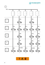
shows an integrated network comprising five
Wallboxes as an example. In an integrated network
of five Wallboxes, the energy supply provides up
to 32 A of current. The Wallboxes are pre-set with
I
max
16 A and I
min
6 A. The total charging current
(32 A) is distributed equally. If a vehicle has ended
its charging process but remains connected to the
Wallbox, this vehicle will continue to be provided
with 6 A of continuous current (for the auxiliary
heater, for example), in some cases alternately with
other vehicles which have already been charged.
2. Installation of the bus system
Installation of the bus system is described below.
The wiring is implemented as line wiring (see 2.2)
or as central wiring (see 2.3).
2.1
General requirements
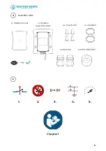
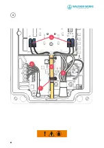
Fig. VIII: Illustration of line wiring and
Fig. XI: Central wiring
1.
Shield connection for the bus lines
2.
Power supply connection
3.
Conductors of the charging cable
4. Connection terminals for bus conductors
5.
Bus insulation
The following requirements must be met for any
type of wiring:
• Always use a screened bus line (e.g. CAT6a) for
the cabling.
• Do not exceed the total permissible fieldbus
length of 500 m.
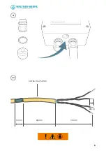
• Prepare the bus cable and the Wallbox for instal-
lation
.
• Ensure that there is sufficient distance between
the conductors, the power supply (2), the
charging cable (3) and the bus lines (5).
• Securely connect the bus lines to the designated
screen connections.
• Cut off unused individual conductors at the end
of the insulation.
2.2
Bus system in line wiring
With line wiring
, the bus
line is routed directly from a Wallbox or external


