15
English
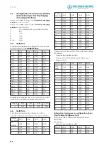
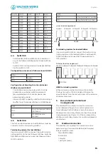
Bus ID
S4/1
S4/2
S4/3
S4/4
3
OFF
OFF
ON
ON
4
OFF
ON
OFF
OFF
5
OFF
ON
OFF
ON
6
OFF
ON
ON
OFF
7
OFF
ON
ON
ON
8
ON
OFF
OFF
OFF
9
ON
OFF
OFF
ON
10
ON
OFF
ON
OFF
11
ON
OFF
ON
ON
12
OFF
ON
OFF
OFF
13
ON
ON
OFF
ON
14
ON
ON
ON
OFF
15
ON
ON
ON
ON
4.4 Switch S5
• Switches S5/1, S5/2 and S5/3 are not needed on
any of the follower Wallboxes. Set these switches
to OFF.
• Switch S5/2 is not required on the leader Wallbox.
Set the switch to OFF.
Configuration as leader and follower via switch S5/4
S5/4
ON
Leader
OFF
Follower
Configuration of blocking function (in leader
Wallbox) via switch S5/3
• The Wallbox has an input via which it can be
blocked by an external switching element
(key-operated switch or similar device; see
assembly instructions).
• Use switch S5/3 to specify whether this blocking is
to affect only the leader Wallbox or all Wallboxes.
S5/3
OFF
Only the leader Wallbox
is blocked.
ON
All Wallboxes are
blocked.
4.5
Switch S6
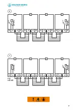
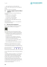
The first and last devices on the RS485 bus must be
connected with a terminating resistor.
Terminating resistor for last Wallbox
Use micro switch S6/2 to connect the built-in termi-
nating resistor on the last follower Wallbox. Switches
S6/1, S6/3 and S6/4 are not used. Set these switches
to OFF position.
S6/2
OFF
Bus termination inactive
ON
Bus termination active
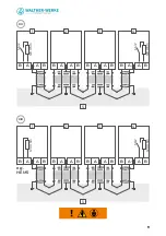
Local load management
Terminating resistor for leader Wallbox
Use micro switch S6/2 to connect the built-in termi-
nating resistor on the leader Wallbox. Switches S6/1,
S6/3 and S6/4 are not used. Set these switches to
OFF position.
External load management
HEMS terminating resistor
When using an external control unit, terminate
the bus line with a 120 ohm resistor. Observe the
specifications from the manufacturer of the external
control system here.
5. Bus protocol (external load
management)
The Modbus RTU protocol is used for communi-
cation between the external control system and
the Wallboxes. Each Wallbox is ready to receive a
Modbus command only after more than 10 seconds
have elapsed since Power On. If the corresponding
Wallbox is in standby mode, it cannot be addressed
via Modbus.
5.1
Modbus connection
The Wallbox is connected to an external control
system using a two-wire RS485 bus (half-duplex).
Bus parameters used:
• Baud 19200 bit/sec,
• 8 data bits,
• 1 stop bit,
• 1 parity bit (even),
Leader
Follower1 Follower2
RS485
S6/2
S6/2
Follower3 Follower4
Leader
HEMS
Follower1 Follower2
RS485
120 Ohm
S6/2
Follower3 Follower4 Follower5


