background image

7

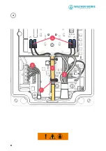
IX

X

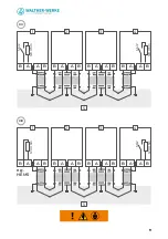
S6

/2

S6

/2

B A

A B

1

B A

A B

2

B A

A B

3

B A

A B

4

12

0 Ohm

12

0 Ohm

B A

A B

1

B A

A B

2

B A

A B

3

B A

A B

4

S6

/2

12

0 Ohm

12

0 Ohm

e.g. 

HEMS

Summary of Contents for basicEVO

Page 1: ...WALLBOX basicEVO basicEVO PRO INSTRUCTION MANUAL walther werke de service...

Page 2: ...2 English 11...

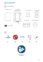
Page 3: ...3 III IV 1 2 3 4 5 Chapter 1 1 x Wallbox Cover 1 x Wallbox basicEVO PRO basicEVO PRO 2 x EADR25 4 x M4x10 T20 1x MFD 25 03 073 2 x ESKV25...

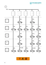
Page 4: ...4 V 32A 1 2 3 4 5 5 1 1 1 4 2 2 2 3 3 3 16A 16A 6A 8A 8A 6A 10A 6A 6A 0A 6A 10A 10A 13A 13A 0A 6A 8A 6A 6A...

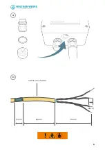
Page 5: ...5 VI CAT6a max 500m 15mm 60mm 70mm 8mm VII...

Page 6: ...6 VIII 3 5 2 1 4...

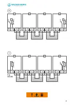
Page 7: ...7 IX X S6 2 S6 2 B A A B 1 B A A B 2 B A A B 3 B A A B 4 120 Ohm 120 Ohm B A A B 1 B A A B 2 B A A B 3 B A A B 4 S6 2 120 Ohm 120 Ohm e g HEMS...

Page 8: ...8 XI 3 5 2 1 4...

Page 9: ...9 B A B A A A B B 1 1 B B A A A B A B 2 2 5 5 B A B A A B A B 3 3 B A A B 4 B A A B 4 S6 2 S6 2 120 Ohm 120 Ohm S6 2 120 Ohm 120 Ohm XII XIII e g HEMS...

Page 10: ...10 XIV S2 S6 S1 S3 S4 S5...

Page 11: ...list for local load management 13 3 4 Check list for external load management 13 4 Configuration of the Wallboxes 13 4 1 Configuration of maximum switch S1 and minimum switch S3 charging current per W...

Page 12: ...basicEVO PRO is used to charge plug in hybrid or electric vehicles Several basicEVO PRO Wallbox units can be operated in an integrated network This enables the power distribution to be monitored for...

Page 13: ...Set the maximum system current in the leader Wallbox Set the maximum and minimum individual charging currents in each Wallbox Set the bus ID in each follower Wallbox Activate the bus terminating resis...

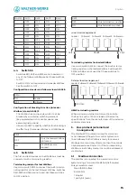
Page 14: ...F OFF ON OFF 4 1 Configuration of maximum switch S1 and minimum switch S3 charging current per Wallbox Rotary switch S1 setting of the maximum charging current from 6 A to 16 A Rotary switch S3 settin...

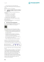
Page 15: ...nating resistor on the last follower Wallbox Switches S6 1 S6 3 and S6 4 are not used Set these switches to OFF position S6 2 OFF Bus termination inactive ON Bus termination active Local load managem...

Page 16: ...the Wallboxes in local load management mode beginning with the leader Wallbox Establish the power supply for all devices in external load management mode beginning with the external control electronic...

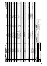
Page 17: ...Control Power Saving if no car plugged 0 enable StandBy Funktion 4 disable StandBy Funktion x reserved development 0 enable 640 Bytes Error Memory reserved manufacturer Support Diagnostic Data 04 rea...

Page 18: ...Contact WALTHER WERKE Ferdinand Walther GmbH Ramsener Stra e 6 D 67304 Eisenberg Germany Fon 49 6351 475 0 Fax 49 6351 475 227 www walther werke de 40 020 0553...

Reviews: