background image

Rev. 1.1


Assembly Instructions - Hand-Spray Valve SMS-15  

Page 12 of 18 


Walther Systemtechnik GmbH 

– D 76726 Germersheim 

Telefon: +49 (0)7274-7022-0 Telefax: +49 (0)7274-7022-91 
http://www.walther-2000.de 

– info@walther-2000.de 


8.3  Maintenance for Operation in Color Marking Systems (normal operation) 

The spray cap will be cleaned every other day with a special thinner and a soft cloth. Make sure that no cloth 
fibers are left on the nozzle tip. 
The material section of the spray valve should be cleaned with a special thinner every other week. Please 
observe the following steps: 


Completely open needle lock (remember raster setting for later use!) 


Remove air cap and unscrew nozzle with a SW 6 open wrench 


IMPORTANT 

Hold spray valve downwards so that no medium can flow into the air channels. Dis-
charged medium will be collected in a container and disposed of later. 


Clean with a soft (paint-)brush and a special thinner.  


Re-assemble nozzle and air cap after cleaning.  


Re-set the raster-needle setting 
 

A cleaning cycle will be initiated after standstills (e.g. breaks over night or on weekends). The nozzle will be 
sprayed clean. This cleaning cycle will be activated through the system controls. 


IMPORTANT 

Use a dummy or a cloth during the cleaning cycle in order to avoid soiling! 

 
After longer system standstills (e.g. 2-3 weeks), the complete system will be cleaned before re-start. If nec-
essary, the material hoses and if applicable, also the inlays of the pressure tank have to be replaced. 
The material pressure container will be opened every week and the color will be thoroughly stirred (if no agi-
tator is provided). 
The material pressure container will be cleaned every 3-4 months; material lines and inlays will be 
exchanged. 

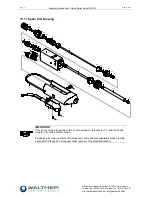
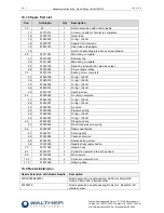
8.4  Replacing Needle (Pos. 1.6), Air Valve (Pos. 4.0) and Nozzle (Pos. 1.1) 

Completely unscrew raster-needle lock (Pos.6.0). Unscrew nozzle extension (Pos.2.1 resp. 2.2) with retainer 
ring (Pos.2.1). Unscrew nozzle (Pos.1.1). Carefully push needle (Pos.7.0) with air valve (Pos.4.0) from the 
nozzle side to the back and carefully extract with a pair of tongs. Install new parts which are slightly greased 
in reverse order. We do not recommend reusing previously employed needles. Leakages can be caused if O-
rings (Pos.3.1) are pinched by needles which are not completely clean. 

8.5  Replacing the Sealing Screw (Pos. 3.0) 

Unscrew raster-needle lock completely (Pos.6.0). Remove nozzle extension (Pos.2.1 resp. 2.2) with retainer 
ring (Pos. 2.1).  Unscrew nozzle (Pos.1.0). Carefully push needle (Pos.7.0) with the air valve (Pos.4.0) from 
the nozzle side to the back and carefully extract with a pair of tongs. Then use a screwdriver SW11 to un-
screw the sealing screw (Pos.3.0) from the thread.  

Summary of Contents for SMS-15

Page 1: ...5 NOTE Please read the Assembly Instructions carefully before first using the incomplete device and strictly adhere to the instructions The incomplete device may only be worked with and worked on by p...

Page 2: ...FINITION OF INTERFACES 8 5 2 MOUNTING AND INSTALLATION 9 5 3 HOSE MOUNTING 9 5 4 CONNECTION DIAGRAM SEPARATE CONTROLS 9 5 5 ADJUSTING THE DEVICE 9 6 OPERATION 10 6 1 GENERAL INFORMATION 10 6 2 OPERATI...

Page 3: ...of 18 Walther Systemtechnik GmbH D 76726 Germersheim Telefon 49 0 7274 7022 0 Telefax 49 0 7274 7022 91 http www walther 2000 de info walther 2000 de 10 1 2 Spare Part List 17 10 2 NOZZLE EXTENSION 17...

Page 4: ...r Stra e 3 D 76726 Germersheim Description Hand Spray Valve Article No S15 We also declare the conformity with other product relevant directives guidelines Mach Direct 2006 42 EU App I Clause 1 1 2 1...

Page 5: ...describe possible property damages IMPORTANT Indicates tips for usage and other particularly useful information No dangerous situation 2 Safety 2 1 General Information The construction of this device...

Page 6: ...or alterations on the device that may hamper its safety without the prior consent of Walther Systemtechnik GmbH Operating the device with defective safety installations or not properly attached or ma...

Page 7: ...justable spray width as well as the integrated spray air valve for pre and post spray And depending on the viscosity of the applicable medium the application image can be adjusted individually via the...

Page 8: ...l Air Pressure bar 4 5 6 Atomizer Air Pressure bar 0 5 5 at least 0 5 bar less than control pressure Material Pressure bar max 35 bar 4 3 Type Label The type label was etched into the casing near the...

Page 9: ...ir black to SL M5 connection SL Pos 2 4 3 Material transparent to M 1 8 connection M Pos 2 3 5 4 Connection Diagram separate controls 5 5 Adjusting the Device The stroke adjustment of the needle will...

Page 10: ...ending on the air and fluid pressures used Ear protection should be worn if required WARNING Danger caused by flammable harmful fluid Always follow the safety instructions on the container or the safe...

Page 11: ...air 8 1 General Information CAUTION Before starting any maintenance or repair work ensure that all air operated tools are depressurized and disconnected from the air supply Before opening the spray va...

Page 12: ...ng cycle in order to avoid soiling After longer system standstills e g 2 3 weeks the complete system will be cleaned before re start If nec essary the material hoses and if applicable also the inlays...

Page 13: ...s 3 1 into the front groove Carefully insert the outer O rings Pos 3 2 and Pos 3 3 into the grooves Slightly grease the complete sealing screw Pos 3 0 and move it back into the main body Pos 4 0 After...

Page 14: ...Spray Image Flat jet Normal Spray Image Round jet Spray image shaped too much upwards and downwards Soiled air cap Soiled nozzle Clean nozzles Spray image too much left sided or right sided Soiled ai...

Page 15: ...ray Valve SMS 15 Page 15 of 18 Walther Systemtechnik GmbH D 76726 Germersheim Telefon 49 0 7274 7022 0 Telefax 49 0 7274 7022 91 http www walther 2000 de info walther 2000 de 10 Appendix 10 1 Dimensio...

Page 16: ...Spare Part Drawing 1 1 1 2 1 3 2 1 1 4 1 5 2 2 2 4 2 3 3 1 3 2 3 3 3 4 3 1 4 1 4 2 4 3 4 4 4 5 4 6 1 6 5 6 1 6 2 6 3 6 4 7 8 8 9 10 11 10 IMPORTANT If the spray valve is equipped with a nozzle extensi...

Page 17: ...ng Viton 3 2 97640019 1 O ring Viton 3 3 97640052 1 O ring Viton 3 4 97640415 1 O ring Viton 3 5 97810102 1 Sealing screw 4 0 97380052 1 Air valve complete 4 1 97640194 1 O ring Viton 4 2 97640027 1 O...

Page 18: ...temtechnik GmbH D 76726 Germersheim Telefon 49 0 7274 7022 0 Telefax 49 0 7274 7022 91 http www walther 2000 de info walther 2000 de 10 3 Accessories Figure Article Number Description 979444 Cleaning...

Reviews: