background image

Rev. 1.1


Assembly Instructions - Hand-Spray Valve SMS-15  

Page 7 of 18 


Walther Systemtechnik GmbH 

– D 76726 Germersheim 

Telefon: +49 (0)7274-7022-0 Telefax: +49 (0)7274-7022-91 
http://www.walther-2000.de 

– info@walther-2000.de 


3  Transport 

3.1  Packaging  

The  type  of  packaging  depends  on  the  individual  mode  of  shipping.  If  not  separately  contracted,  the 
packaging  is  in  accordance  with  the  rules  and  regulations  of Walther  Systemtechnik  GmbH. This  rule  is  in 
accordance with the Federal Association for Packaging HPE. 


3.2  Tasks before Transport 

The following has to be done before transport:  

  Disconnect all power lines.  

The actual transport of the incomplete device and its individual parts requires special care in order to prevent 
damages  from  external  forceful  impact  or  careless  on-  and  off-loading.  Depending  on  the  mode  of 
transportation, suitable transport and load securing has to be selected. The incomplete device will be aligned 
and leveled by appropriate fastening elements

.  


4  Description of Function  

4.1  Purpose of the Device 
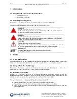
 

CAUTION 

The use of other media can cause functional failures, damages or even the destruction 
of the device. 

 
The  spray  valves  of 

SMS-15

  series  are  suitable  for  the  application  of  liquid  up  to  viscous  media,  such  as 

grease, oil,  abherents,  colors  or  glues.  Major  characteristics  of  the  hand-spray  valve  are  the  steplessly  ad-
justable spray width as well as the integrated spray air valve for pre- and post-spray. And depending on the 
viscosity of the applicable medium, the application image can be adjusted individually via the nozzle size or 
the  atomized  air  pressure  or  also  the  material  pressure.  Three  different  hoses  are  supplying  atomized  air, 
control air and medium. 
Spray  valve 

SMS-15

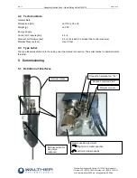
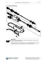
  is  a  pneumatically  controlled  application  device.  The  air  valve  (Pos.4.0)  is  connected 

with the  needle  (Pos.1.6)  and  receives  air  supply  from  the  optional  3/2-way  magnetic  valve. This  results  in 
the  opening  movement  of  the  air  valve  (Pos.4.0)  so  that  atomizer  air  is  released  (pre-spray).  The  spring 
(Pos.4.4)  has  to  be  completely  compressed  before  the  air  valve  (Pos.4.0)  will  move  the  needle  (Pos.1.6), 
and then the material will be discharged from the nozzle. When the control air is turned off or fails, the spring 
(Pos.5.0) will initiate the closing movement of the needle; first the needle closes the nozzle and after that the 
air valve (post-spray) is locked. Pre- and post-spray are required for keeping the nozzle (Pos.1.1) clean.  
The material supply pressure (1/8” connection – Pos.2.3) has to be adapted to the desired spray image and 
also to the atomizer air pressure (M5 connection “ZL” – Pos.2.4). 
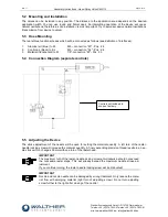
Spraying  can  be  performed  as 

continuous  or  intermittent.  The  control  air  pulses  (M5  connection  “SL”  – 

Pos.2.4) will be directed to the working piston via the 3/2-way magnetic valve (optional). 
Depending  on  the  individual  area  of  operation,  the  control  air  pressure  has  to  be  adapted  to  the  operating 
cycles. 


Summary of Contents for SMS-15

Page 1: ...5 NOTE Please read the Assembly Instructions carefully before first using the incomplete device and strictly adhere to the instructions The incomplete device may only be worked with and worked on by p...

Page 2: ...FINITION OF INTERFACES 8 5 2 MOUNTING AND INSTALLATION 9 5 3 HOSE MOUNTING 9 5 4 CONNECTION DIAGRAM SEPARATE CONTROLS 9 5 5 ADJUSTING THE DEVICE 9 6 OPERATION 10 6 1 GENERAL INFORMATION 10 6 2 OPERATI...

Page 3: ...of 18 Walther Systemtechnik GmbH D 76726 Germersheim Telefon 49 0 7274 7022 0 Telefax 49 0 7274 7022 91 http www walther 2000 de info walther 2000 de 10 1 2 Spare Part List 17 10 2 NOZZLE EXTENSION 17...

Page 4: ...r Stra e 3 D 76726 Germersheim Description Hand Spray Valve Article No S15 We also declare the conformity with other product relevant directives guidelines Mach Direct 2006 42 EU App I Clause 1 1 2 1...

Page 5: ...describe possible property damages IMPORTANT Indicates tips for usage and other particularly useful information No dangerous situation 2 Safety 2 1 General Information The construction of this device...

Page 6: ...or alterations on the device that may hamper its safety without the prior consent of Walther Systemtechnik GmbH Operating the device with defective safety installations or not properly attached or ma...

Page 7: ...justable spray width as well as the integrated spray air valve for pre and post spray And depending on the viscosity of the applicable medium the application image can be adjusted individually via the...

Page 8: ...l Air Pressure bar 4 5 6 Atomizer Air Pressure bar 0 5 5 at least 0 5 bar less than control pressure Material Pressure bar max 35 bar 4 3 Type Label The type label was etched into the casing near the...

Page 9: ...ir black to SL M5 connection SL Pos 2 4 3 Material transparent to M 1 8 connection M Pos 2 3 5 4 Connection Diagram separate controls 5 5 Adjusting the Device The stroke adjustment of the needle will...

Page 10: ...ending on the air and fluid pressures used Ear protection should be worn if required WARNING Danger caused by flammable harmful fluid Always follow the safety instructions on the container or the safe...

Page 11: ...air 8 1 General Information CAUTION Before starting any maintenance or repair work ensure that all air operated tools are depressurized and disconnected from the air supply Before opening the spray va...

Page 12: ...ng cycle in order to avoid soiling After longer system standstills e g 2 3 weeks the complete system will be cleaned before re start If nec essary the material hoses and if applicable also the inlays...

Page 13: ...s 3 1 into the front groove Carefully insert the outer O rings Pos 3 2 and Pos 3 3 into the grooves Slightly grease the complete sealing screw Pos 3 0 and move it back into the main body Pos 4 0 After...

Page 14: ...Spray Image Flat jet Normal Spray Image Round jet Spray image shaped too much upwards and downwards Soiled air cap Soiled nozzle Clean nozzles Spray image too much left sided or right sided Soiled ai...

Page 15: ...ray Valve SMS 15 Page 15 of 18 Walther Systemtechnik GmbH D 76726 Germersheim Telefon 49 0 7274 7022 0 Telefax 49 0 7274 7022 91 http www walther 2000 de info walther 2000 de 10 Appendix 10 1 Dimensio...

Page 16: ...Spare Part Drawing 1 1 1 2 1 3 2 1 1 4 1 5 2 2 2 4 2 3 3 1 3 2 3 3 3 4 3 1 4 1 4 2 4 3 4 4 4 5 4 6 1 6 5 6 1 6 2 6 3 6 4 7 8 8 9 10 11 10 IMPORTANT If the spray valve is equipped with a nozzle extensi...

Page 17: ...ng Viton 3 2 97640019 1 O ring Viton 3 3 97640052 1 O ring Viton 3 4 97640415 1 O ring Viton 3 5 97810102 1 Sealing screw 4 0 97380052 1 Air valve complete 4 1 97640194 1 O ring Viton 4 2 97640027 1 O...

Page 18: ...temtechnik GmbH D 76726 Germersheim Telefon 49 0 7274 7022 0 Telefax 49 0 7274 7022 91 http www walther 2000 de info walther 2000 de 10 3 Accessories Figure Article Number Description 979444 Cleaning...

Reviews: