5.0 INSTALLATION AND FIXING
2
SEP.SEPCOM_Vertical.--.M.A4.0722.EN Issue: A4
07.22
27
SEPCOM
®
Vertical
!
FEEDING PUMP
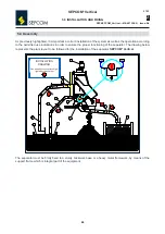
The feeding pump (
B
) is positioned 400 / 500 mm
(
H1
) from the bottom of the tank (
A
) for the
product to be treated to prevent foreign solid bodies from entering.
Consider in a rated cross-section (
Q
) ø of 100 mm, an inlet flow of 20 m
3
/h for the version V2-
150-3 and of 30 m3/h* for the version V2-200-3.
The pump has to be sized by taking into account all load losses occurring on the flow path from
the tank to the inlet (
D
).
!
FEEDING PIPE
Connect feeding pipe (
C
) to the material inlet pipe (
D
); avoid pressing, widening and choking it.
!
RETURN PIPE
Connect return pipe (
F
) to the material outlet pipe (
E
) provided on hopper (
G
); avoid pressing,
widening and choking it or narrowing of the section.
Position it with a slope of at least 5°.
The free end of the pipe has to be at least 200 mm (
H2
) from the tank level (
A
) for the material
to be handled.
!
SEPARATED LIQUID DRAIN PIPE
Connect drain pipe (
N
) to the outlet hopper (
M
); avoiding sinking, crushing, bends or narrowing
of the section.
The drain pipe must have a straight length of at least 200 mm and has to be placed outside the
connecting stub; position it with a minimum slope of 5°.
The free end of the pipe has to be at least 200 mm (
H3
) from the level of the separated liquid
tank (
P
).
!
ELECTRICAL CONNECTIONS
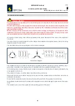
Connect the motor terminal (
L
) to the electrical system, and check the direction of rotation of
the screw.
*
The hydraulic flow rate is intended theoretical with clean water; the actual value depends on the material type, on the configuration of
the equipment and on the maintenance.


