background image

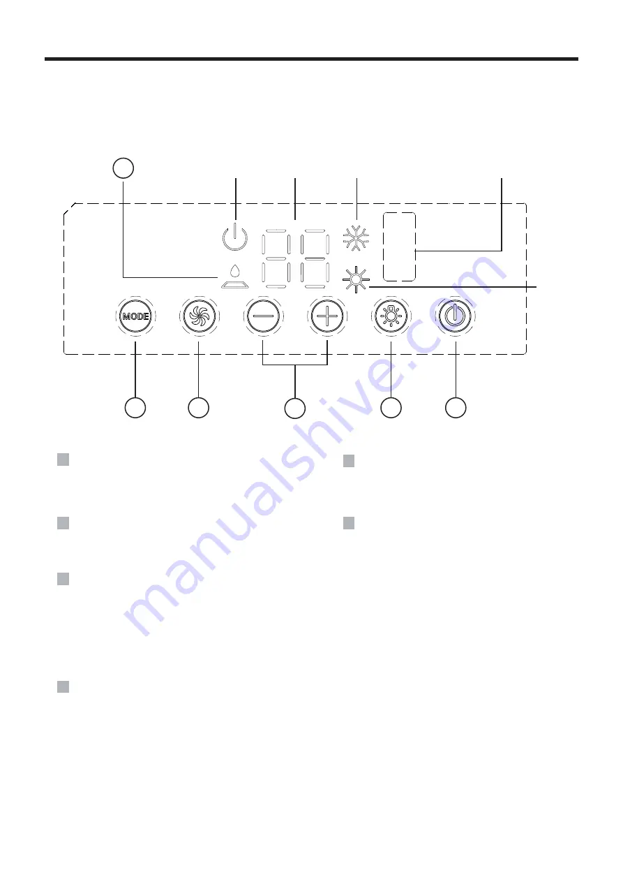
CONTROL PANEL

Note: If the remote controller is missing, operate on the control panel.  

6

5

4

3

2

1

- 1

2

-

ON/OFF

indicator

temp.

indicator

COOL

indicator

receiver

window

HEAT

indicator

2

LIGHT button 

Press this button to turn on or turn off display

light on indoor unit.

3

(+/-)  button 

4

FAN SPEED button 

Select the fan speed LOW, MED, HIGH and TURBO 
in sequence.  

Press the + button to increase the set(operating)
temperature of the unit,and press the - button to
decrease the set(operating) temperature of the 

1

ON/OFF button

Operation starts when pressing this button, and  
stops when pressing this button again.

5

MODE button 

Select the operation mode, COOL,

FAN, 

HEAT.

6

FILTER CHECK indicator

This feature is a reminder of cleaning the air 
filter(normal maintenance) for more efficient 
operation. The light will turn on automatically
after the fan works more than 250 hours.
If the light is on, turn off and power off the 
unit, take the air filter out and clean it, then
re-install the air filter, power on and turn
on the unit, the light will still be on, press
+ button for 5s,the light will turn off.

unit. the temperature setting range is from 16~30

o

(61~86 F).

Summary of Contents for Air-con 2500W

Page 1: ...ung Dachklimaanlage Modell wamovo air con 2500W Vielen Dank dass Sie sich für ein Produkt von wamovo entschieden haben Bitte lesen Sie die Bedieungsanleitung sorgfältig vor Einbaubeginn durch und bewahren Sie diese auf ...

Page 2: ...INHALTSVERZEICHNIS Modell max Zsys unit ohms wamovo air con 2500W 0 316Ω ...

Page 3: ...leund andere Risiken auszuschließen Arbeitstemperaturbereich Empfohlener Arbeitstemperaturbereich 4 46 Heizung 4 24 Kühlung 18 46 Das Außengerät schaltet den Betrieb ab aufgrund verschiedener Schutzarten innerhalb des Arbeitstemperaturbereichs Bevor Sie das Gerät einschalten öffnen Sie bitte die horizontale Jalousie des Innengeräts von Hand Andernfalls kann die kühle Luft nicht ausgeblasen werden ...

Page 4: ...oses The grounding resistance should comply with national electric safety regulations 1 Must follow the electric safety regulations when installing the unit For appliances with type Y attachment the instructions shall contain the substance of the following If the supply cord is damaged it must be replaced by avoid a hazard Properly connect the live wire neutral wire and grounding wire of power soc...

Page 5: ... einen qualifizierten Elektriker Prüfen Sie die vorhandene Stromversorgung und beheben Sie eventuelle Verdrahtungsprobleme BEVOR Sie das Gerät installieren und in Betrieb nehmen Dieses Klimagerät ist für den Betrieb an einer 220 240V AC 50Hz 1 Phase Stromversorgung ausgelegt 1 Vielen Dank dass Sie sich für eine Dachklimaanlage von wamovo entschieden haben Diese Anleitung enthält notwendige Informa...

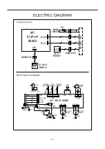
Page 6: ...EGN YEGN PE PE M1 4YV VT VT 4WAY N CN5 IN_FAN AP1 MAIN BOARD BN OUT_FAN OUT_FAN1 BU N1 AC L1 YEGN POWER PE BU RD M2 M3 BU C YEGN YEGN PE PE OUTDOOR TUBE SENSOR TUBE SENSOR OUTROOM SENSOR 4 WAY VALVE IN_FAN MOTOR PE ELECTRIC BOX RT1 20K WH RT2 20K BK RT3 15K CN4 WIFI_CON DISP1 DISP2 L N K1 COMP CAP WH S COMP OUT_FAN MOTOR OUT_FAN MOTOR R COMP YEGN PE INDOOR UNIT ...

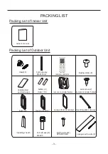
Page 7: ...ernbedienung Doppelseitig gummiertes Papier Schrägschraube 2 Fernbedienungshalterung Fernbedienungshalterung Schaumstoff Oberseite Schaumstoffzubehör Schaumstoffzubehör Montageplatte Unterlage Isoliermantel Bolzenschraube 4 M6X25 Blechschraube 4 ST4 2X25 MA Schwamm Kabelbinder 2 Batterien 2 AAA 1 5V 3 ...

Page 8: ...nhalt oder Position der Anzeige kann von der obigen Grafik abweichen bitte beachten Sie das tatsächliche Produkt Fernbedienung Äußere Einheit Gehäuse Lufteinlassgitter Abflussöffnung Chassis HINWEIS Das tatsächliche Produkt kann von den obigen Grafiken abweichen bitte sehen Sie sich die tatsächlichen Produkte an 4 ...

Page 9: ...EMP Taste TIMER OFF Taste TURBO Taste Turbo mode Set time TIMER ON TIMER OFF Kindersicherung Licht Dimmer Lüfterdrehzahl einst Bestätigen Temperatur einst Temperaturanzeige Temperatur einst Außentemperatur Innentemepratur Sleep mode Clock Heat mode Fan mode Dry mode Cool mode Auto Modus Betriebsweise Dies ist eine allgemeine Fernbedienung Einige Modelle haben diese Funktion andere nicht Bitte bezi...

Page 10: ...Cool Dry Fan und Heat auszuwählen Der Auto Modus ist die Standardeinstellung beim Einschalten Im Automatikmodus wird die Temperatur nicht angezeigt im Heizmodus ist der Anfangswert 28 C 82 F in den anderen Modi ist der Anfangswert 25 C 77 F AUTO COOL DRY FAN HEAT Nur für Kühl und Heizgerät Bei einem Gerät das nur kühlt erfolgt keine Aktion wenn es das Signal für den Heizbetrieb empfängt Dies ist e...

Page 11: ...üftergeschwindigkeit ist zwingend erforderlich Taste 7 Drücken Sie diese Taste die Uhr kann eingestellt werden das Signal blinkt und wird angezeigt Innerhalb von 5 Sekunden kann der Wert durch Drücken der Taste oder eingestellt werden Wenn Sie diese Taste 2 Sekunden lang gedrückt halten wird der Wert auf der Zehnerstelle der Minute alle 0 5 Sekunden um 1 erhöht Während des Blinkens drücken Sie die...

Page 12: ...ngeräts auszuwählen Wenn das Innengerät zum ersten Mal eingeschaltet wird zeigt es die Einstellungstemperatur an wenn der Temperaturanzeigestatus von einem anderen Status auf geändert wird zeigt es die Umgebungstemperatur an 5 Sekunden später oder innerhalb von 5 Sekunden wenn es ein anderes Fernbedienungssignal empfängt kehrt es zur Anzeige der Einstellungstemperatur zurück wenn die Benutzer den ...

Page 13: ...ie Betriebsart AUTO RUN gewählt ist wird die eingestellte Temperatur nicht auf dem LCD Display angezeigt sondern das Gerät richtet sich automatisch nach der Raumtemperatur um die geeignete Betriebsart zu wählen und die Umgebung angenehm zu gestalten TURAO EUNKTION Wenn Sie diese Funktion starten läuft das Gerät mit superhoher Lüftergeschwindigkeit um schnell zu kühlen oder zu heizen damit sich die...

Page 14: ...Taste oder um die gewünschte Temperatur einzustellen Es ist nicht notwendig die Temperatur im AUTO Modus einzustellen Drücken Sie die FAN Taste um die Lüftergeschwindigkeit einzustellen Sie können zwischen LOW MID und HIGH wählen Drücken Sie die Taste um die Schaukel auszuwählen Durch drücken der Tasten TIMER ON und TIMER OFF können den geplanten Timer ein oder ausschalten Drücken Sie die Taste LI...

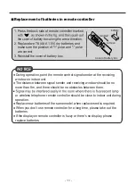
Page 15: ...ngerät Der Abstand zwischen Signalsender und Empfangsfenster sollte nicht mehr als 8 m betragen und es sollten sich keine Hindernisse dazwischen befinden Das Signal kann leicht in einem Raum gestört werden in dem sich eine Leuchtstofflampe oder ein schnurloses Telefon befindet Die Fernbedienung sollte sich während des Betriebs in der Nähe des Innengeräts befinden Tauschen Sie neue Batterien des gl...

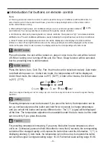
Page 16: ...Sie es aus nehmen Sie den Luftfilter heraus und reinigen Sie ihn setzen Sie dann den Luftfilter wieder ein schalten Sie das Gerät ein und schalten Sie es ein das Licht leuchtet immer noch drücken Sie die Taste für 5s das Licht schaltet sich aus Der Betrieb startet wenn Sie diese Taste drücken und stoppt wenn Sie diese Taste erneut drücken LICHT Taste Drücken Sie diese Taste um die Displaybeleuchtu...

Page 17: ...stgelegt ist Es muss eine verstärkte und gerahmte Dachöffnung geschnitten werden falls keine Öffnung vorhanden ist oder Sie können vorhandene Lüftungsöffnungen verwenden FALL A Wenn an der gewünschten Montagestelle für das Klimagerät bereits eine Dachentlüftung vorhanden ist müssen die folgenden Schritte durchgeführt werden 1 Entfernen Sie alle Schrauben mit denen die Dachluke am Fahrzeug befestig...

Page 18: ...achen Eine typische Ausgleichsscheibe ist in Abbildung 3 dargestellt 3 Nachdem das Klimagerät auf dem Dach nivelliert wurde kann eine zusätzliche Unterlegscheibe über der inneren Deckenmontage erforderlich sein Die Dachklimaanlage und die Innendeckenbaugruppe müssen rechtwinklig zueinander sein bevor sie miteinander befestigt werden 4 Nachdem der Bereich für die Montagebohrungen ordnungsgemäß vorb...

Page 19: ... Max Abbildung 2 Hinweis Stellen Sie das Gerät zum Betrieb möglichst auf eine waagerechte Fläche Das Gerät kann nur kurzzeitig bei einem maximalen Neigungswinkel von 5º betrieben werden um das Austreten von Wasser zu verhindern Level Höhe variiert um Gerät eben zu machen Abbildung 3 1018 356x356 ÖFFNUNG 15 Level Level 356 542 650 576 120 356 ...

Page 20: ...ßengehäuses nicht an siehe Abbildung 4 1 2 Befestigen Sie das Außengerät auf dem Dach des Fahrzeugs und bohren Sie dann Löcher 3 Platzieren Sie das Außengerät auf dem Fahrzeugdach heben Sie das Außengerät an und platzieren Sie das Außengerät nach dem Bohren von Löchern auf dem Fahrzeugdach Ziehen Sie das Außengerät nicht Andernfalls kann der Dichtungsstreifen abfallen siehe Abbildung 4 2 Abbildung...

Page 21: ...5 1 Tragen Sie dann das Außengerät auf das Fahrzeugdach und richten Sie es an den Öffnungen auf dem Fahrzeugdach aus Verwenden Sie 2 Sätze Montageplatten und 4 Schrauben um das Außengerät zu montieren siehe Abb 5 Sie müssen die Befestigungsschrauben von Hand anziehen einschrauben um ein Überdrehen zu vermeiden STARTEN SIE DIE MONTAGEBOLZEN NICHT MIT EINER DRUCKLUFTPISTOLE Die Montageschrauben soll...

Page 22: ...toff Abb 5 2 Abb 5 3 SCHRITT 4 ELEKTRISCHE VERDRAHTUNG VERLEGUNG DER 220 240 V WECHSELSTROMVERKABELUNG 18 WARNUNG Vergewissern Sie sich dass alle Stromzuführungen zum Gerät unterbrochen sind bevor Sie Arbeiten am Gerät durchführen um die Möglichkeit eines Stromschlags oder einer Verletzung und oder einer Beschädigung des Geräts zu vermeiden Nachdem der innere Deckenmontagerahmen ordnungsgemäß an d...

Page 23: ...liermantel um die Verdrahtung zu umschließen Klemmen und Schwamm Kleben Sie dann den Wärmedämmmantel auf und befestigen Sie ihn mit Kabelbindern Hinweis 1 Kabelbinder müssen an dem Bereich mit dem Schwamm und der Wärmeisolierhülle angebracht werden 2 Legen Sie die Wärmeisolierhülle vor der Installation der Frontplatte des Innengeräts auf den Luftkanal ...

Page 24: ...auben Windkanal Frontblende Frontblende Abb 10 Filter 2 3 Überprüfen Sie die Position des Thermostats Stellen Sie sicher dass der Thermostat durch die Halteführung geführt wird und keine Metallfläche berührt Befestigen Sie das Deckengitter mit 4 Schrauben am Windkanal der Deckenmontage siehe Abbildung 10 Bringen Sie den gesunden Filter und das Lufteinlassgitter an Drücken Sie PUSH und verriegeln S...

Page 25: ...wenn das Fahrzeug geparkt ist Achten Sie auf eine korrekte und waagerechte Ausrichtng der Klimaanlage Stellen Sie die Fernbedienung auf eine niedrigere Temperatureinstellung zurück Entfernen und reinigen Sie den Filter Lassen Sie dem Gerät ausreichend Zeit um den Raum zu kühlen Die Befestigungsschrauben sollten gleichmäßig angezogen werden indem die Dichtung der Bodenplatte zusammengedrückt wird D...

Page 26: ...eustart des Geräts behoben werden Wenn nicht wenden Sie sich bitte an qualifiziertes Fachpersonal für den Service Stellen Sie sicher dass die Netzspannung nicht weniger als 184V beträgt Sie kann nach einem Neustart des Geräts behoben werden Wenn nicht wenden Sie sich bitte an qualifiziertes Fachpersonal für den Service PL Bitte wenden Sie sich für den Service an qualifiziertes Fachpersonal H1 Bede...

Page 27: ... Sie das Lufteinlassgitter und nehmen Sie dann den Filter heraus 1 Konkrete Demontagemethode Verwenden Sie das ähnliche Werkzeug wie in Abbildung B richten Sie den Klammerkern aus und setzen Sie ihn ein wie in Abbildung A gezeigt Die Einstecktiefe beträgt ca 3 mm wie in Abbildung C gezeigt wodurch die Klammer abnehmbar ist Wenn Sie ein Geräusch hören knicken Sie den Verschlusskern mit den Händen u...

Page 28: ...ine geeignete Länge die Ihrem Handgefühl entspricht WARNUNG NICHTBEACHTUNG DER ANWEISUNGEN KANN ZU SCHWEREN VERLETZUNGEN FÜHREN 1 Berühren Sie die Kondensatorklemmen nicht ohne die elektrische Entladung der Kondensator kann immer noch die hohe Spannung haben auch wenn die Stromversorgung ausgeschaltet ist 2 Seien Sie vorsichtig wenn Sie das Kühlsystem warten das einen hohen Innendruck aufweist 3 B...

Page 29: ......

Page 30: ... Original Instructions Recreational Vehicle Air Conditioner model wamovo air con 2500W Thank you for choosing our product Please read this Owner s Manual carefully before operation and retain it for future reference ...

Page 31: ...CONTENTS 5 2 3 3 18 20 7 6 3 3 4 modesl max Zsys unit ohms Wamovo Air con 2500W 0 316Ω TROUBLESHOOTING GUIDE 21 ERROR CODE 22 ...

Page 32: ...oil or fumes in the air 5 The place with sulfureted gas 6 Other places with special circumstances 7 This air conditioner unit is only used for the vehicle without concave and convex surface on the top of it 8 Prohibit operating this air conditioner unit when starting up the vehicle or when the vehicle is driving 9 Prohibit supplying the power for the air conditioner unit with the vehicle power sup...

Page 33: ...proceeding any work related to electricity and safety 4 5 with specialized grounding device by a professional Please make sure it is always grounded effectively otherwise it may cause electric shock can t be used for other purposes The grounding resistance should comply with national electric safety regulations Requirements Forelectric Connection Safety precaution 1 For appliances with type Y atta...

Page 34: ...ou have any questions about the following instructions contact a qualified electrician Check the available power supply and resolve any wiring problems BEFORE installing and operating this unit This air conditioner is designed to operate from a 220 240V AC 50Hz 1 Phase power supply 1 Thank you for choosing the recreational vehicle air conditioner by wamovo This manual will supply you with all the ...

Page 35: ...ssembly YEGN YEGN PE PE M1 4YV VT VT 4WAY N CN5 IN_FAN AP1 MAIN BOARD BN OUT_FAN OUT_FAN1 BU N1 AC L1 YEGN POWER PE BU RD M2 M3 BU C YEGN YEGN PE PE OUTDOOR TUBE SENSOR TUBE SENSOR OUTROOM SENSOR 4 WAY VALVE IN_FAN MOTOR PE ELECTRIC BOX RT1 20K WH RT2 20K BK RT3 15K CN4 WIFI_CON DISP1 DISP2 L N K1 COMP CAP WH S COMP OUT_FAN MOTOR OUT_FAN MOTOR R COMP YEGN PE INDOOR UNIT ...

Page 36: ...te controller double sided gummed paper sunk screw 2 remote controller holder remote controller holder foam up foam accessory sponge foam accessory mounting plate sub assy insulating sheath bolt sub assy 4 M6X25 tapping screw 4 ST4 2X25 MA sponge and bundle 2 battery 2 AAA 1 5V Packing List of Outdoor Unit 3 ...

Page 37: ...rol panel membrane Display content or position may be different from above graphics please refer to the actual product remote controller Outdoor Unit Outer case Air in grille Drainage outlet Chassis NOTICE Models may be different from above graphics please refer to the actual product 4 ...

Page 38: ...ton TURBO button 13 SLEEP button 14 LIGHT button CLOCK button button Turbo mode Send signal Set temperature Set time TIMER ON TIMER OFF Child lock Light Up down swing Set fan speed Temp display type Set temp Outdoor ambient temp Indoor ambient temp Sleep mode Clock Heat mode Fan mode Dry mode Cool mode Auto mode Operation mode This is a general remote controller Some models have this function whil...

Page 39: ...at mode can be selected circularly Auto mode is default while power on Under Auto mode the temperature will not be displayed Under Heat mode the initial value is 28 C 82 F Under other modes the initial value is 25 C 77 F AUTO COOL DRY FAN HEAT Only for cooling and heating unit As for cooling only unit it won t have any action when it receives the signal of heating operation This is a general use r...

Page 40: ... mode and change fan speed manually button 7 Press this button the clock can be set up signal blink and display Within 5 seconds the value can be adjusted by pressing or button if continuously press this button for 2 seconds above in every 0 5 seconds the value on ten place of minute will be increased 1 During blinking repress the clock button signal will be constantly displayed and denotes the se...

Page 41: ...al that will return to display the setting temperature if the users haven t set up the temperature displaying status that will display the setting temperature This function is applicable to partial of models After powered on the setting temperature displaying is defaulted according to cust omers requirements to display if there is no requirement that will default to display the presetting temperat...

Page 42: ...ndoor fan will run at low fan speed 10s later the unit will turn off If start this function the unit will run at super high fan speed to cool or heat quickly so that the ambient temp approachs the preset temp as soon as possible When AUTO RUN mode is selected the setting temperature will not be displayed on the LCD the unit will be in accordance with the room temp automatically to select the suita...

Page 43: ... it is powered on the guide louver of main unit will close automatically Pressing or button to set the desired temperatur It isunnecessary to set the temp at AUTO mode Pressing FAN button set fan speed can sele LOW MID and HIGH Press TIMER ON and TIMER OFF button can set the scheduled timer on or timer off Press LIGHT button to control the on and off of t displaying part of the unit This function ...

Page 44: ...he receiving window on indoor unit The distance between signal sender and receiving window should be no more than 8m and there should be no obstacles between them or wireless telephone remote controller should be close to indoor unit during operation Replace new batteries of the same model when replacement is required When you don t use remote controller for a long time please take out the batteri...

Page 45: ...rating temperature of the 1 ON OFF button Operation starts when pressing this button and stops when pressing this button again 5 MODE button Select the operation mode COOL FAN HEAT 6 FILTER CHECK indicator This feature is a reminder of cleaning the air filter normal maintenance for more efficient operation The light will turn on automatically after the fan works more than 250 hours If the light is...

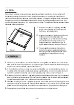
Page 46: ... structures Once the location for your air conditioner has been determined A reinforced and framed roof hole opening must be cut if there is no hole or you may use existing vent holes CASE A If a roof vent is already present in the desired mounting location for the air conditioner the following steps must be performed 1 Remove all screws which secure the roof vent to the vehicle Remove the vent an...

Page 47: ...sing occurs A typical support frame is shown in Figure 1 CAUTION 1 The roof top air conditioner must be mounted on a level plane from front to rear and side to side when the vehicle is parked on a level plane Figure 2 shows maximum allowable degrees that the unit can be mounted above or below level 2 If the roof of the vehicle is sloped not level such that the roof top air conditioner cannot be mo...

Page 48: ... Level 0 Max Figure 2 Note Try you best to put the unit on the horizontal surface for operation The unit can only operate for a short time at the maximum sloping angle of 5º for preventing water leakage Level Height Varies to Make Unit Level Figure 3 1018 356x356 OPENING 15 Level Level 356 542 650 576 120 356 ...

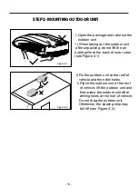
Page 49: ...lle at the back of outer case see Figure 4 1 2 Fix the outdoor unit at the roof of vehicle and then drill holes 1 Place the outdoor unit at the roof of vehicle lift the outdoor unit and then place the outdoor unit after drilling holes at the roof of vehicle Do not drag the outdoor unit Otherwise the sealing strip may fall off see Figure 4 2 Figure 4 1 Figure 4 2 ...

Page 50: ... long See fig 5 1 Then carry the outdoor unit to the vehicle s top and align with the openings on the vehicle s top Use 2 sets of mounting plate assembly and 4 screw bolts to mount the outdoor unit See fig 5 You must start thread themounting bolts by hand to avoid cross threading DO NOT START THE MOUNTING BOLTS WITH AN AIR GUN The mounting bolts should be tightened process is completed when the ba...

Page 51: ... foam Num 3 14mm sponge Num3 5mm wind path foam foam under fig 5 2 fig 5 3 STEP 4 ELECTRICAL WIRING ROUTING 220 240V AC WIRING 18 WARNING Make sure that all power supply to the unit is disconnected before performing any work on the unit to avoid the possibility of shock or injury and or damage to the equipment After the interior ceiling assembly frame is properly secured to the roof top air condit...

Page 52: ... insulating jacket to enclose the wiring terminals and sponge Then glue the thermal insulating jacket and fasten it with cable ties Note 1 Cable ties must be attached to the area with both sponge and thermal insulating jacket 2 Before installing the front panel of indoor unit put the thermal insulating jacket on top of the air duct ...

Page 53: ...atus 4 screw wind path front panel front grill fig 10 filter 2 3 Check the thermostat position Make sure the thermostat is routed through the holding guide and is not touching any metal surface Secure the ceiling grille to the ceiling assembly wind path with 4 screws see Figure 10 Install the healthy filter and air intake grill Press PUSH and lock with clasps To complete the installation and syste...

Page 54: ...rear and side to side when the vehicle is parked Make sure that the mounting of the air conditioner is correct and level Reset the remote control to a lower temperature setting Remove and clean the filter Allow a sufficient amount of time for unit to cool the room Mounting bolts should be tightened evenly by compressing the basepan gasket The filter is dirty Remove and clean the filter The room wa...

Page 55: ...nated after restarting the unit If not please contact qualified professionals for service Make sure the power voltage is not less than 184V It can be eliminated after restarting the unit If not please contact qualified professionals for service PL Please contact qualified professionals for service H1 Means defrosting status It s the normal phenomenon Note If there re other error codes please conta...

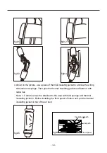
Page 56: ... core and insert it as Figure a is shown The inserted depth is about 3mm as shown in Figure c which the clasp is detachable When you hear a sound buckle the clasp base with your hands to take out the clasp Note If you insert it too deep the clasp might be blocked compulsory dismantle will damage the clasp and it might be invalid At this moment use the tool whose diameter is smaller than the clasp ...

Page 57: ...riate length that fits your hand feeling WARNING FAILURE TO FOLLOWING INSTRUCTIONS COULD RESULT IN SERIOUS PERSONAL INJURY 2 Be careful when you maintain the refrigeration system which has the high internal pressure 3 Do not block the filter and the indoor air inlet badly to prevent water leakage 1 Don t touch the capacitor terminals without the electric discharge the capacitor still may have the ...

Page 58: ......

Reviews: