Page | 16
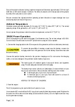
Even with suitable carburetor jetting, engine horsepower will decrease approximately 3.5% for each
1000 feet or 305 meter increase in altitude. The effect of altitude on the horsepower will be greater
than this if the carburetor is not re-jetted.
Be sure to restore the original jet before operating at lower elevation or engine damage due to an
excessively lean fuel mixture may occur.
Ambient Temperature
Generator power generally degrades 1% for every 10° F (5.5° C) above 85° F (29° C). The normal
operating range of the generator is -20° to 113° F (-29° to 45° C).
Do not operate the generator when the ambient temperature is above 113° F (45° C)
12VDC Power Operation
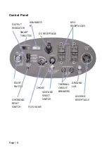
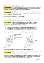
The DC receptacle may be used for charging 12 volt batteries only. The no load voltage is 15V-30V.
Turn the Smart Throttle switch to the OFF position when using the DC receptacle.
1. Connect the charging cable to the DC receptacle of the generator and then to the battery terminals.
To prevent the possibility of creating a spark near the battery, connect the
charging cable first to the generator then to the battery. Disconnect the cable
first at the battery.
Connect the positive battery terminal to the positive charging cord. Do not reverse the charging
cables, or serious damage to the generator and/or battery may occur.
The battery gives off explosive gases; keep spark, flames and cigarettes
away. Provide adequate ventilation when charging.
The battery may contain sulfuric acid (electrolyte). Contact with skin or eyes
may cause severe burns. Wear protective clothing and a face shield.
If electrolyte gets on your skin, flush with water.
If electrolyte gets in your eyes, flush with water for at least 15
minutes and call a physician.
KEEP OUT OF REACH OF CHILDREN.
2. Start the engine
The DC receptacle may be used while the AC power is in use.
An overloaded DC circuit will trip the DC circuit fuse located behind the generator panel. Replace the
fuse with one of the same size and rating (6.3A slow-blow 5x20mm). Use of a higher rated fuse may
lead to generator damage.
Summary of Contents for WI6000
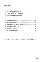
Page 1: ...Inverter Series Generator Operator Manual Model WI6000 May 2017 P N 220884 Rev A ...
Page 2: ......
Page 4: ...Page 2 ...
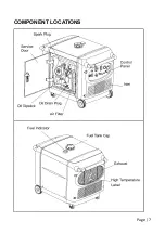
Page 9: ...Page 7 COMPONENT LOCATIONS ...
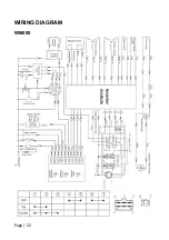
Page 24: ...Page 22 WIRING DIAGRAM WI6000 ...
Page 25: ......
Page 26: ......
Page 27: ......
Page 28: ......


