See
the
table
of
contents
sec on
for
knife
changing
and
installa on.
Loosen
the
planing
head
locking
knob
(54
‐
21).
To
ini ally
begin
planing,
set
the
head
posi on
to
a
height
1/32”
less
than
the
di
‐
mension
of
the
stock
entering
the
machine.
One
‐
third
of
a
turn
on
the
eleva ng
handle
will
equal
1/32”.
Tighten
the
head
locking
knob.
Make
sure
the
chip
extractor
is
in
place,
the
front
lip
engaged
into
the
head
and
the
pin
is
fi
rmly
seated.
U lize
a
high,
square,
relieved
guide
when
planing
the
edge
of
stock
to
ensure
the
edge
will
be
reasonably
square.
A
relief
in
the
ver cal
wall
of
the
guide
reduces
fric on.
See
the
guide
sec on
for
a
picture
of
the
edge
guides.
THREAD LOCKING INFORMATION
A
medium
strength
thread
‐
locking
compound
used
on
some
parts
prone
to
loosen
with
vibra on.
Use
two
drops
on
the
thread
area
of
the
parts
listed
below.
P
‐
122
post
side
axle.
54
‐
16
Rest
pins.
54
‐
15
Pivot
screws.
A
small
tube
of
thread
locker
is
available
for
purchase.
Part
number
P
‐
242
Do
not
use
on
P
‐
124
in
‐
feed
axle,
or
on
P
‐
224,
out
‐
feed
axle.
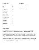
THICKNESS
TYPE OF WOOD
DEPTH OF CUT
1”
Poplar
¼”
1”
Red Oak
3/16”
3”
White Pine
3/16”
3”
White Oak
1/8”
6”
Poplar
1/8”
6”
Red Oak
1/16”
Summary of Contents for 20210492060001
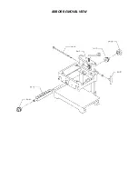
Page 19: ...ARBOR REMOVAL VIEW...
Page 20: ...Stand exploded diagram...
Page 22: ...Notes Maintenance Records...


