background image

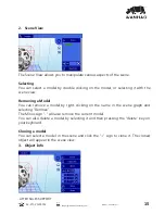
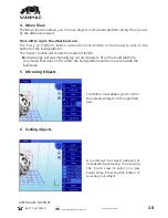
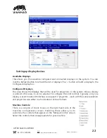
From  this  screen  we  will  be  able  to  control  the  motors  of  the  printer  

(Note  hood  must  be  on  

the  printer)

,  which  means  displacing  the  build  base  over  the  Z  axis,  as  well  as  controlling  the  

LCD.

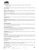
In  this  section  of  the  Control  screen  we  have  the  buttons  that  will  allow  us  to  move  

                                      the  Z  position  of  the  build  base.  As  you  can  see,  we  have  4  buttons  for  

                                      each  direction,  50,  10,  1  and  0.1  mm.  Using  the  value  indicated  as  z

                                      Rate  (at  the  bottom)  you  can  change  the  speed  of  progress  measured  in


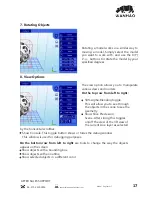
ŎÞĶĶÞŎsǼsNjǣˀŎÞŘȖǼsʳɟsĶǣŸʩŘ_ǼÌsÌŸŎsEȖǼǼŸŘʳǻÌÞǣÞǣǣÞŎÞĶNjÞŘ¯ȖŘOǼÞŸŘ

                                      to  the  button  that  we  have  described  above  in  the  3D  View  screen,  that  is,  if  

                                      you  click  it,  the  whole  build  base  will  rise  to  the  detector  limit,  where  it  will  seek

                                      the  zeros  of  each  axis,  then  descend  to  a  lower  position.  The  descent  is  

_ŸŘsʩNjǣǼ¯ǣǼǼÌsŘǣĶŸɠʳǻÌÞǣÌŸŎsĶǣŸÞŘOĶȖ_sǣǣǼ¶sɠÌsNjsǼÌsEȖÞĶ_Eǣs

raises  to  a  higher  position  so  as  to  be  able  to  prepare  the  machine  to  pour  the  resin  in  and  

eave  it  ready  to  lower  the  base  and  start  printing.

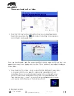
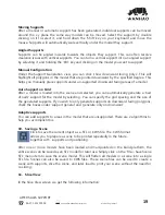
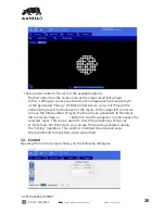
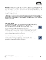
With  this  box  you  can  control  the  image  exposed  by  the  LCD  with  the  following  options:

-­      Show  Calibration:  A  red  grid  is  projected.  This  will  

allow      you  to  check  if  your  projector  is  well  focused  -­on  

the  vat  bottom.

Show  Blank:  A  black  screen  is  shown,  meaning  a  screen  

that  won't  cure  the  resin  instantly.

-­    Hide:  This  option  hides  the  slice  projection  screen,  

allowing  the  projector  to  display  the  main  desktop  

background  (the  extended  part).

-­      Edit   Commands:   This   option   allows   you   to   edit  

commands  to  control  the  projector.  Fields  beneath  this  

are  not  of  recommended  use.

ˠˢʳNŸŘʩ¶ȖNjs

ˠˢʳˠNŸŘʩ¶ȖNjsōOÌÞŘs

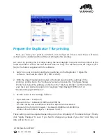
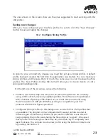
              Machine  Connection  COM  Port

Once   a   Machine   profile   has   been   selected,   the   ‘Configure’   button   on   the   ‘Machine  

Connection’  box  can  be  selected  to  show  the  Connection  setup  screen.

This  screen  allows  you  to  choose  the  correct  COM  port  and  speed  to  communicate  with  the  

printers’  controller  card  via  serial  connection.

*NOTE  

–  The  current  version  of  the  application  will  allow  connections  up  to  

115200  bps.  

ƻĶsǣssŘǣȖNjsɴŸȖNjOŸŘǼNjŸĶĶsNjʩNjŎɠNjsÞǣOŸŘʩ¶ȖNjs_¯ŸNjǼÌsǣƼss_OÌŸǣsŘʳ

AFTER  SALES  SUPPORT

86-­571-­23290996

support@wanhao3dprinter.com

Model  :  Duplicator  7

21

Summary of Contents for DUPLICATOR 7

Page 1: ...WANHAO DUPLICATOR 7 USER MANUAL...

Page 2: ......

Page 3: ...issues with this product or it s performance is not what you had expected please contact us at WANHAO before returning the item to the store It is likely that we can resolve any problems for you via p...

Page 4: ...l rights and remedies in respect of the product that the consumer has under the China laws In case you purchase from WANHAO distributor your warranty shall be covered by distributor s Warranty and hon...

Page 5: ...peration MOVING PARTS Do not leave the WANHAO 3D Printer unattended during operation Always wear the glove while handling resin or printing object s O s s s O s s s _ sO s O s _ s s s Es s s_ s _ s OO...

Page 6: ...printer com Model Duplicator 7 The principle behind your printer Safety Information 5 5 Disposal instructions 6 Cleaning the machine and your printed objects Detailed Creation workshop software instru...

Page 7: ...d the ecology but there is a huge performance advantage in that there is no unnecessary energy created All of the available photons strike photoinitiators and hand over their energy In comparable Digi...

Page 8: ...equivalent 4 5 meters 15 feet maximum In case of malfunction disconnect the printer immediately from network s _ O E s s s O s expose you to dangerous voltage points or other risks Refer all reparatio...

Page 9: ...deo output of your computer 2 USB cable to connect your computer to the printer s Os s s plastic spatula 200gr of UV resign Recommended items Gloves Paper towels industrial alcohol Soft brush or spong...

Page 10: ...and open Screen resolution Set your screens to Multiple Displays and extend this display mode keeping your monitor as the main screen N s O s s O ss s _ s O s _ s s that it does not have the power sav...

Page 11: ...O s E s sO s s s O s s O s your resin and desired resolution for example Hard Daylight 100micron or Standard Daylight 100micron s s s s s s _ layer thickness 0 100 mm exposure time between 18 000 and...

Page 12: ...in any way O sO s Os s O ss O sO s s s s E sO is in contact with the build base If it is above the build platform it will not adhere If you click on the view box located in the bottom left corner you...

Page 13: ...contact with the screen by pressing lightly when it is on and it will appear white in the corners You can check the screen is working by pressing the show calibration button located in the Control ta...

Page 14: ...ithout the possibility of damaging it 4 Check it is thoroughly clean then place it in a container for 10 20 minutes in an area with bright sunlight You can use light from a UV lamp When it has been co...

Page 15: ...ed to run the application as Administrator Main screen N O s s s s D O s Os s s s N s s N O s s O s E sO N s s N you to prepare a scene to be printed repeatedly in the future together with supports an...

Page 16: ...upports in this function Clicking this button accesses the Slicing screen You can see the individual slices that have been generated as well as the G code This allows you to control the z axis motor h...

Page 17: ...icking on the name in the scene graph and selecting Remove The Minus sign will also remove the current model You can also delete a model by selecting it and then pressing the delete key on your keyboa...

Page 18: ...uild platform The Center button will center the model at 0 0 0 s O _s s E _ _s _ s s E _ Es s_ _s s build area 5 Mirroring Objects 6 Scaling objects The Mirror view allows you to mirror s s sO s_ E sO...

Page 19: ...the scene to see the geometry Show Slice Preview on Scene After slicing this toggles on off the view of the 3D view of the current slice layer as selected by the horizontal scrollbar Show Console This...

Page 20: ...a model to the build space Because of the nature of DPP the lower layers must be supported by the supports s _s Os s s Adding a single Support A single support can be generated by clicking the manual...

Page 21: ...an automatically generate a bed of nails support for the model by selecting You can specify the grid spacing and the size of the generated supports If you wish to only generate supports on downward fa...

Page 22: ...of layers that have been generated In the lower left corner we have a button to turn the projector on and expose the selected layer This can be useful to check the positioning of the vat G Code View...

Page 23: ...tart printing With this box you can control the image exposed by the LCD with the following options Show Calibration A red grid is projected This will allow you to check if your projector is well focu...

Page 24: ...__s_ s O Es s sO s_ O s s N O O s display is used Creation Workshop can support 2 projectors each with the same resolution and projection size either in a horizontal or vertical format Machine Control...

Page 25: ...profiles The Slice Profiles Config tab item will allow you to create delete or edit a O _ E _ s On the left side of the screen we can see the following s s _ _ E s O s sO s s s s O s s E s s s s O s...

Page 26: ...Costs menu item Lift and Sequence Time s sO s sO _ s _ s O s s Os s O s the Auto Calc button to generate a time estimate for the lift and retract This value may ss_ Es _ s_ E s_ s ss_ O s Lift Distan...

Page 27: ...e just the gcode for the scene will be generated and the images will be rendered during build time Build Direction Top down or Bottom up This value determines which direction the Lift occurs For a bot...

Page 28: ......

Page 29: ...air You should also be aware that rather than repairing goods we may replace them with refurbished goods of the same type or use refurbished parts in the repair process Please be assured though refurb...

Page 30: ......

Reviews: